


84
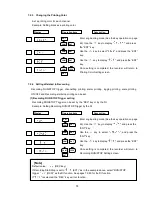
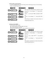
Example: When calibrating the RTD at Channel 2
Enter engineering mode (See the key operation on page
69). Use the
key to display "
", and press
the “ENT” key.
Use the
key to select "
", and press the “ENT”
key.
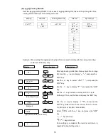
Select a channel to which equipment for calibration such
as a dial resistor is connected, and press the “ENT” key.
Enter 100
. After 10 seconds, make sure that the ALM
indicator is unlit and press the “ENT” key.
Enter 150
. After 10 seconds, make sure that the ALM
indicator is unlit and press the “ENT” key.
Enter 300
. After 10 seconds, make sure that the ALM
indicator is unlit and press the “ENT” key.
If the calibration is correct, select "
" with the
key, and if incorrect, select "
" with the
key. Then, press the “ENT” key.
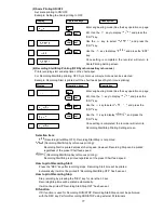
[Note]
When calibrating RTD for a channel, short-circuit the other input terminals except the calibrating
channel. RTD calibration is required for every channel.
[Note]
During calibration, the ALM indicator shows the following conditions.
(1) When the ALM indicator is unlit:
(2) When the ALM indicator is flashing:
The calibration is within the range.
The recorder is assessing the input value.
(3) When the ALM indicator is lit:
The calibration is out of the range.
Make sure that the connection
is proper and input is correct.
If calibration is performed out of the input range, calibration value out of the input range will be
fixed, and
(Voltage) or
(RTD) will be displayed when the unit returns to
measurement mode. At this time, return the calibration value to the default value using the function
in Section 7.2.8 Initializing the Setup Data and Calibration Data.
: The indicator is unlit.
: The indicator is lit.
ENT
ENT
ENT
ENT
ENT
ENT
ENT
ENT
Display
Operation keys
Description
CH.No
CH.No
CH.No


