


102
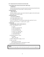
(3) Calibration of Reference Junction Compensation
Calibrate the reference junction compensation in the case of thermocouple input.
(Example) Connecting the input to Channel 1, and setting the calibration when the thermocouple
input value is -0.5 (input 0 ), and the measured RJC temperature is 24.5 .
1) Check the Process variable when impressing 0.000 mV 2 V to Channel 1 by the
voltage generator beforehand. (In this example, it is -0.5 .)
2) Check the terminal temperature of Channel 1 at the data calibration in engineering
mode (Reference junction compensation). (In this example, it is 24.5 .)
3) Add the difference (0.5 ) to the true value, then set as a correct RJC temperature.
[24.5 – (–0.5)=25.0 ]
Calibrate RJC according to the instructions in Section 7.2.12 Data Calibration (Calibration of
reference junction compensation). (See Section 7.2.12 Data Calibration on p.83.)
Freezing Point
Cold Junction
Compensator
(Iced Water)
Precision
Voltage(Current)
Generator
HR-706 Recorder
Input Terminals
Digital
Voltmeter
+
+
-
-
-
-
+
+
Be sure to attach terminal covers.
Thermocouple wires or Compensation lead wires
Copper wires
Wiring
+
-
+
-
+
-
[Note]
(1) This calibration is conducted when compensation by the recorder's built-in temperature
sensing element (INT: internal compensation) is selected as a reference junction
compensation method.
(2) Wire Channel 1 and Channel 4 to calibrate.
(3) After wiring, attach the terminal covers and wait for 5 minutes or longer, then perform
calibration.
Calibration


