


20
4.3 DI Function/Alarm Output Wiring (Optional)
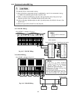
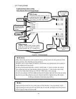
4.3.1 DI function/Alarm Output Wiring Example
Fig. 4.3.1-1 DI Function Wiring Example
Fig. 4.3.1-2 Alarm Output Wiring Example
WARNING
(1) Be sure to wire after turning power OFF.
(2) When the power source has been connected to the Alarm output, turn off that power source.
(3) When a hazardous voltage is supplied to the alarm terminal:
a) Never touch terminals. b) Attach covers to terminals. c) Wires should be double shielded.
d) Use ring-type solderless terminal connectors with an insulation sleeve.
CAUTION
Precautions for Wiring the DI function
(1) DI function input has a built-in drive power source. Do not apply an external voltage to a DI
function input terminal.
(2) A DI function input contact capacity should be a withstanding voltage of 50 V DC, 16 mA or
more, ON resistance of 20
max. (Wiring resistance included).
(3) Do not use unused terminals as relay terminals.
Precautions for Wiring the Alarm Output
(1) An alarm output contact capacity is as follows.
250 V AC: 3 A max. (Resistive load)
30 V DC:
3 A max. (Resistive load)
125 V DC: 0.5 A max. (Resistive load)
0.1 A max. L/R= 7 ms max. (Inductive load)
(2) Attach an anti-surge protective circuit (surge absorbers, etc.) to an output terminal, when
required.
(3) Attach a round solderless terminal with an insulation sleeve (for M3.5) to the end of an
electric wire.
(4) Keep alarm output wiring away from the input wiring.
(5) Do not use unused terminals as relay terminals.
Terminal Block
+12V
Recorder Side
COM
Load
1A
~
6A
Terminal Block
Recorder Side
DI1
~
3
DI.COM
1C
~
6C
CAUTION
The DI function (optional) consists of 3 Digital inputs.
The alarm output consists of 6-Relay output (Normally open).


