


18
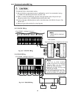
4.2.1 Wiring Procedure
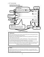
Fig. 4.2.1-1 Input Wiring for Each Channel
(1) Put your fingers on the left and right hooks of the transparent protective cover on the input
terminal block. Pushing them in, pull the cover toward you.
(2) Wire the input lines, referring to Fig. 4.2.1-1, Fig. 4.2.1-2 and Fig. 4.2.1-3. (p.19)
(3) Attach transparent protective covers.
mV, V inputs
Thermocouple input
Fig. 4.2.1-2 Input Wiring (mV, V, Thermocouple inputs)
CAUTION
To remove the transparent protective cover, release the left and right (both sides) hooks
simultaneously. If they are released one after the other, the cover may be damaged.
4 +
B
4 -
B
4
A
5 +
B
5 -
B
5
A
6 +
B
6 -
B
6
A
DI
COM
DI
3
DI
2
DI
1
TD
RD
SG
1 +
B
1 -
B
1
A
2 +
B
2 -
B
2
A
3 +
B
3 -
B
3
A
A
B
B
+
-
+
-
A
B
B
+
-
+
-
A
B
B
+
-
+
-
+
-
DC voltage
Thermocouple
RTD
Direct current
CH1
CH2
CH3
CH4
CH5
CH6
+
-
B
B
A
+
-
B
B
A
+
-
+
-


