AL-2020/2035/2040/2050/2060 COPY PROCESS 6 - 4
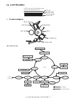
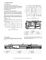
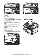
Step-7: Optical discharge (Semiconductor laser)
Before the drum rotation is stopped, the semiconductor laser is
radiated onto the drum to reduce the electrical resistance in the
OPC layer and eliminate residual charge, providing a uniform state
to the drum surface for the next page to be printed.
When the electrical resistance is reduced, positive charges on the
aluminum layer are moved and neutralized with negative charges
on the OPC layer.
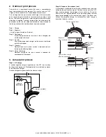
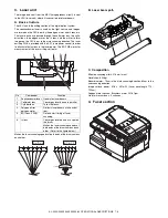
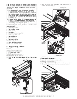
Charge by the Scorotron charger
Function
The Scorotron charger functions to maintain uniform surface
potential on the drum at all times, It control the surface potential
regardless of the charge characteristics of the photoconductor.
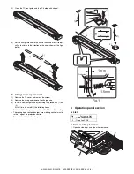
Basic function
A screen grid is placed between the saw tooth and the photocon-
ductor. A stable voltage is added to the screen grid to maintain the
corona current on the photoconductor.
As the photoconductor is charged by the saw tooth from the main
corona unit, the surface potential increases. This increases the
current flowing through the screen grid. When the photoconductor
potential nears the grid potential, the current turns to flow to the
grid so that the photoconductor potential can be maintained at a
stable level.
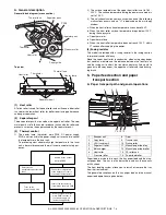
Process controlling
Function
The print pattern signal is converted into an invisible image by the
semiconductor laser using negative to positive (reversible) devel-
oping method. Therefore, if the developing bias is added before
the drum is charged, toner is attracted onto the drum. If the devel-
oping bias is not added when the drum is charged, the carrier is
attracted to the drum because of the strong electrostatic force of
the drum.
To avoid this, the process is controlled by adjusting the drum
potential and the grid potential of the Scorotron charger.
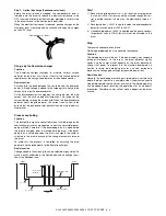
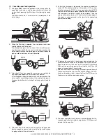
Basic function
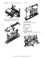
Voltage added to the screen grid can be selected, high and low. To
make it easily understood, the figure below shows voltage transi-
tion at the developer unit.
Start
1) Because the grid potential is at a low level, the drum potential
is at about -400V. (Carrier may not be attracted though the car-
rier is pulled towards the drum by the electrostatic force of -
400V.
2) Developing bias (-400V) is applied when the photoconductor
potential is switched from LOW to HIGH.
3) Once developing bias (-400V) is applied and the photo conduc-
tor potential rises to HIGH, toner will not be attracted to the
drum.
Stop
The reverse sequence takes place.
Retaining developing bias at an abnormal occurrence
Function
The developing bias will be lost if the power supply was removed
during print process. In this event, the drum potential slightly
abates and the carrier makes deposits on the drum because of
strong static power. To prevent this, the machine incorporates a
function to retain the developing bias for a certain period and
decrease the voltage gradually against possible power loss.
Basic function
Normally, the developing bias voltage is retained for a certain time
before the drum comes to a complete stop if the machine should
stop before completing the normal print cycle. The developing bias
can be added before resuming the operation after an abnormal
interruption. Therefore, carrier will not make a deposit on the drum
surface.
Semiconductor laser
0
START
STOP
Print potential
Toner attract
potential
2)
3)
1)
Low
4)
High
Drum potential
Developing bias
Time
Summary of Contents for AL-2020
Page 217: ...Memo ...


