


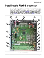


Installing the FlexPS processor
FlexPS Product Guide
Page 55
Jumper settings
The processor includes two sets of jumpers, the cable selection jumpers and the terminator
bypass jumpers (see
The cable selection jumpers (T6, T15, T7 - Channel A; T14, T16, T11 - Channel B) are used to
specify the type of sensor cable that is connected to Channel A and Channel B. Each of the
jumpers provides two selections, FIXED and LOOSE.
•
Place the shunt on the FIXED side if MEX sensor cable is used for the corresponding channel.
•
Place the shunt on the LOOSE side if Mark 2 sensor cable is used for the corresponding
channel.
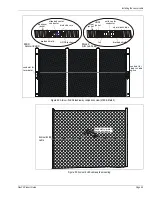
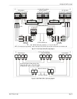
Figure 62: Connecting Mark 2 sensor cable to the processor
1
2
3
5
4
6
Pass the sensor cable through one of the enclosure’s
Insert the center conductor into the right side terminal (+)
Twist the shield into a single conductor, and remove
Separate the exposed braided shield.
6.4 mm (0.25 in.) of the foil covered insulator from
and the shield into the left side terminal (-) and tighten
Insert the terminal block into T10 (FLEX CH A / FLEX CH B)
small cable glands. Carefully, remove 1.5 cm of the
outer black jacket.
the center conductor.
the screws.
and tighten the cable gland. Verify that the center conductor
Repeat steps 1, 2, 3, 4, and 5 for the second cable.
goes to the + terminal and the shield goes to the - terminal.
Remove 5 mm of the foil covering
from the clear tube insulator.