


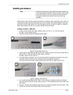


Installing the sensor cable
Page 38
FlexPS Product Guide
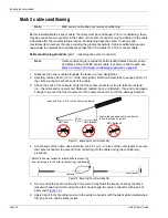
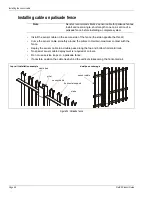
Sliding gates with cable protection
Protect sliding gates by installing sensor cable on the gate panel, and connecting it to the sensor
cable on the fence with lead-in cable.
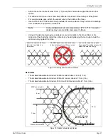
1.
Run the sensor cable around the perimeter of each gate panel from top center to top center,
with a 20 cm (8 in.) overlap.
2.
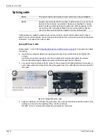
Determine the length requirements for the lead-in cable.
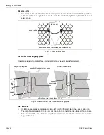
3.
Using cable ties, bundle two lead-in cables together and secure the bundle to one gate at the
location indicated.
For a double sliding gate, repeat for the second gate.
4.
Run a bypass cable from one side of the gate to the other.
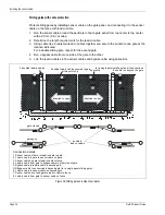
5.
Join the lead-in cables to the sensor cables and bypass cable using splice kits.
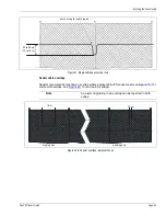
Figure 38: Sliding gate on inside of perimeter
1
2
3
4
5
6
7
8
splice kits
2 bundled lead-in cables
bundled lead-in cables secured to gate
bundled
gate closed
gate open
Connection details
1. Sensor cable on fence to lead-in cable to gate.
2. Lead-in cable to gate to sensor cable on gate.
3. Sensor cable on gate to lead-in cable to fence.
4. Lead-in cable from gate to bypass cable to other side of gate.
5. Bypass cable to lead-in cable to second gate.
6. Lead-in cable to sensor cable on second gate.
7. Sensor cable on second gate to lead-in cable to fence.
8. Lead-in cable from gate to sensor cable on fence.
direction to open
direction to open
at this point only
for a single gate install a splice kit and continue
the cable run beyond the gate
OR Bypass cable to sensor cable beyond gate (for a single panel sliding gate).
lead-in cables