


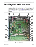


Installing the FlexPS processor
Page 54
FlexPS Product Guide
If excessive noise is present, or becomes evident after installation, check the integrity of the
sensor cable installation. In particular, ensure that there is no inadvertent ground connection to the
coaxial cable shield at either end of a splice connection or terminator. Verify that the center
conductor and shield have not been swapped at the terminal block.
Sensor cable/lead-in cable connections
An enclosure that is installed on a post on the protected fence can use a direct connection to the
sensor cable. If the enclosure is installed away from the protected fence, or away from the start of
the sensor zone, then the connection to the processor must be made with lead-in cable. The lead-
in cable is spliced to the sensor cable at the start point of the zone. The sensor cable to processor
connections are made on removable terminal blocks. First, prepare the cables. Then install the
cables in the terminal block and connect the terminal block to the sensor cable inputs (Flex
Channel A, Flex Channel B). Sensor cable and lead-in cable connections are made exactly the
same way.
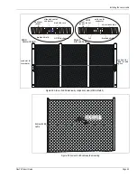
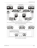
illustrates the sensor cable connection procedure for MEX sensor cable.
illustrates the sensor cable connection procedure for Mark 2 sensor cable.
Figure 61: Connecting MEX sensor cable to the processor
1
2
3
4
5
Pass the sensor cable through one of the enclosure’s
Insert the center conductor into the + terminal
Twist the shield into a single conductor, and remove
Separate the exposed braided shield.
6.4 mm (0.25 in.) of the insulator from the center
and the shield into the - terminal, and tighten
Insert the terminal blocks into T10 (FLEX CH A / FLEX CH B) and
small cable glands. Carefully, remove 1.5 cm of the
outer black jacket.
conductor.
the screws.
tighten the cable glands. Verify that the center conductors go to the
Repeat steps 1, 2, 3 and 4 for the second cable.
+ terminals and the shields go to the - terminals.