


Setup
Page 74
FlexPS Product Guide
Setup
Processor setup requires configuring the inputs and outputs (I/O) and for network based
processors, specifying the network configuration.
Specify the Auxiliary I/O control mode
This section details the procedures for configuring the processor’s I/O for Local control and
Remote control operation.
1.
On the Aux Cfig tab select the Arrow beside the Aux Control: field.
2.
Specify the control mode for this processor (Local or Remote).
3.
Select the Download button to save the configuration changes to the processor.
Auxiliary (Aux) inputs
The two Aux inputs on the FlexPS processor are voltage sensing inputs. The processor
determines an input’s status via an internal reference voltage, and the configuration of the contact
closures and supervision resistors. Input contact closures MUST be voltage-free. You define the
inputs as normally open (NO) or normally closed (NC) with single resistor supervision, dual
resistor supervision, or unsupervised. The Filter Window parameter allows you to set the time
period for which an input must be active, before the processor reports an event.
Local control mode
In local control mode, the two Aux inputs are dual purpose inputs for self-test and audio activation
(AUX1 = A-side, AUX2 = B-side). You can setup the Aux inputs to perform both functions, either
function, or no function. To activate the self-test function, close a momentary switch across the
input. You must close the momentary switch for the time specified in the Filter Window. To activate
the audio function, close a switch with a 5.1 k
series resistor across the input. Leave the AUX
inputs open if you do not want to use the self-test or audio functions.
shows the input
wiring configuration for Local control mode:
Remote control mode
In Remote control mode, the two Aux inputs serve as auxiliary device inputs to the host computer.
The inputs are available for reporting the status of other security devices. The processor reports
any change of an input’s state to the head end system.
includes the selectable Remote
Control input wiring configurations, and
includes the selectable supervision resistor
values.
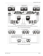
Figure 76: Local Control Mode input wiring
1
T
T = self-test switch
speaker = audio switch
1 = 5.1 k series resistor