


Perimeter layout guidelines
FlexPS Product Guide
Page 13
Perimeter layout guidelines
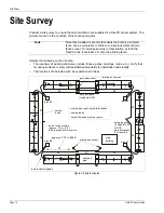
Use a site plan to mark the locations for the FlexPS components:
•
Sensor cable - indicate the cable layout for each zone.
•
Lead-in cable - Indicate the layout if lead-in cable is being used (at the processor, for a
bypass).
•
Cable connectors - indicate the type of connection (splice, terminator).
•
FlexPS processors (note the addresses for network based processors).
•
Power supply - indicate the type of power supply and the power distribution plan.
•
Alarm communication wiring (relay output or network alarm communications).
Sensor cable selection rules
There are two types of sensor cable available for use with the FlexPS system, MEX cable and
Mark 2 cable. MEX cable uses a fixed center conductor and contains a permanent electrical
charge. Mark 2 cable uses a loose center conductor inside a clear tube and generates an electrical
signal through the triboelectric effect.
Figure 5: Mark 2 and MEX sensor cable reels
150 m (492 ft.) reel
Mark 2 sensor cable
300 m (984 ft.) reel
MEX sensor cable