


Installing the FlexPS processor
Page 56
FlexPS Product Guide
The two terminator bypass jumpers (T12 and T13) are used on processors that employ a single
channel (A or B), and for troubleshooting purposes to help identify cable faults.
•
Install the shunt at T12 if a properly terminated sensor cable is NOT connected to Channel A.
•
Install the shunt at T13 if a properly terminated sensor cable is NOT connected to Channel B.
•
Remove the shunt at T12 if a properly terminated sensor cable is connected to Channel A.
•
Remove the shunt at T13 if a properly terminated sensor cable is connected to Channel B.
If a properly terminated sensor cable is not connected to a cable input, and the appropriate jumper
is not installed, the processor will report a constant supervision alarm on that channel.
Relay outputs
The FlexPS processor includes four Form C relays. Each relay has an associated LED, which
indicates when the relay is active. Each relay has a common connection to either a Normally Open
(NO) or Normally Closed (NC) relay contact.
Relay contact ratings
The dry contact relays are single pole, double throw, Form C, latching, rated for 30 V @ 1 A max.
In Remote control mode, you can configure the relays as latching (ON by command, OFF by
command), in flash mode (ON-OFF-ON-OFF, etc. by command, then OFF by command), or pulse
mode (ON for a period, then OFF). For flash and pulse modes, the relay Active/Inactive times are
selectable. In Local control mode the relays remain active for the event’s duration or for the
selectable Hold Time, whichever is longer.
Auxiliary inputs
AUX 1 and AUX 2 are voltage sensing inputs. The processor determines an input’s status via an
internal reference voltage, and the configuration of the contact closures and supervision resistors.
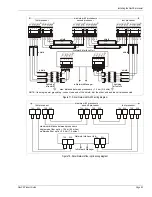
provides wiring diagrams for self-test, audio activation, and auxiliary device inputs.
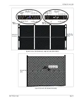
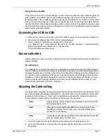
Figure 63: FlexPS jumper settings
CAUTION
The contact closure inputs to AUX 1 and AUX 2 MUST be
voltage-free.
cable selection
jumper set for
MEX sensor cable
terminator bypass
jumpers “parked”
on 1 pin
(not installed)
cable selection
jumper set for
Mark 2 sensor cable
terminator bypass
jumpers installed
for both channels