Mach-DSP User’s Manual
Document Number: MACH-DSP-9021
Page 73
www.ScannerMAX.com
Four-channel display; selecting waveforms
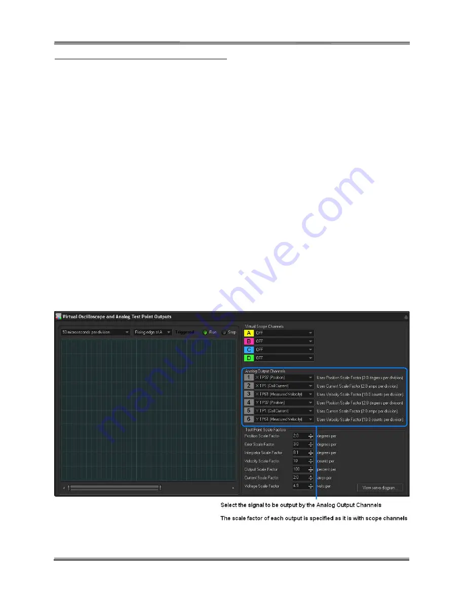
Up to four channels can be displayed at the same time, each having its own color. The
channels are called Channel A, Channel B, Channel C, and Channel D. Waveforms for
a particular channel are selected using the drop-down list. In the list you will find test
point numbers as well as a description of the selected signal. Press the button labeled
“View servo diagram” to see a full list of the test point numbers, and their meaning.
On normal oscilloscopes, each channel has its own vertical sensitivity control. One
channel might be showing 1 volt per division while another channel is showing 20 volts
per division. The Oscilloscope found in the Mach-DSP does not offer a separate vertical
sensitivity for each channel. Instead, signals of like-type are grouped together, and a
single sensitivity is offered for all signals in a particular group. For example, the
Command Input and Position signals share the same group, and thus have a single
scale factor. This makes sense, since you often want to see the position signal in
relation to the command signal, to check for tracking errors. The scale factor for each
group of signals is adjusted using the spinners found on the bottom/right side of the
Oscilloscope window.
Analog Output channels
In a similar way in which oscilloscope channels are selected, individual signals within
the servo loop can be routed to user-defined analog outputs on the same window.
(Details about the Analog Outputs can be found in Section 3.5 of this manual.)
IMPORTANT!
All Oscilloscope and Analog Output selections are stored as a part of the
tuning! It is important to select (or deselect) the channels you want before saving.


