Mach-DSP User’s Manual
Document Number: MACH-DSP-9021
Page 35
www.ScannerMAX.com
6.3
Raster (saw-tooth) waveforms
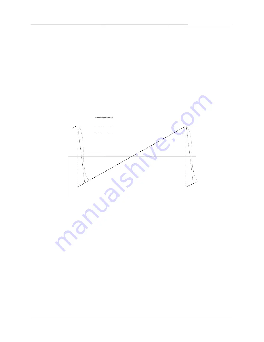
There are three types of raster command waveforms (See Figure 6.3). The easiest to
generate and lowest performance command is a waveform that commands an
instantaneous retrace of the scanner. The scanner cannot follow an instantaneous
retrace, which causes it to operate at an angle that is smaller in amplitude than
commanded. Performance can often be improved by the use of a dual slope command
waveform. The slope of the retrace portion of the command is generally determined
through trial and error, but a good starting point is 70% of the expected retrace time.
The ideal raster command waveform is determined by taking the second integral of a
square acceleration profile of a magnitude equal to the maximum unsaturated
acceleration of the scan system.
The parameters of interest for a raster waveform are typically velocity linearity and
retrace time. The velocity of the scanner can be observed by monitoring the velocity
signal using the built-in oscilloscope, or by routing a velocity signal to one of the
external user test points. The position signal can also be overlaid on the oscilloscope to
determine the active scan angle.
Retrace time is typically minimized by increasing the
error
gain, while using the
damping
adjustment to maintain a smooth settling on the velocity waveform. The integrator term
is used to maintain a constant velocity over the active scan region.
Figure 6.3: Raster Waveforms
Dual Slope
Structured
Instantaneous Retrace


