Mach-DSP User’s Manual
Document Number: MACH-DSP-9021
Page 60
www.ScannerMAX.com
A final note about using Mode 2…
Although the cable resistance, coil resistance, coil inductance, and Back EMF voltage
may be known, we recommend that these values be fine-tuned using the built-in
oscilloscope, while monitoring Motor I*R (TP84) and Coil Temperature (TP22). Also
note that Mode 2
will not
work properly with the ScannerMAX Compact 506 scanner.
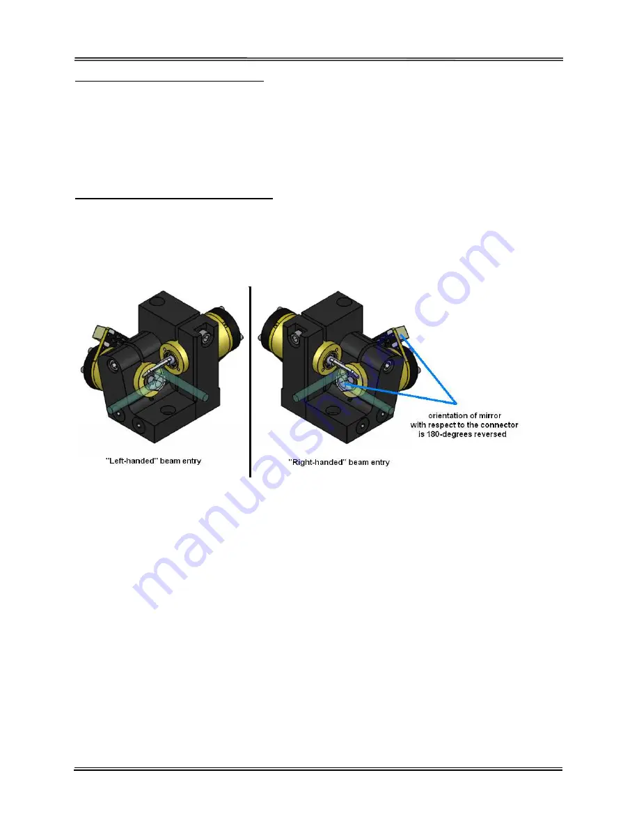
Motor drive (mirror) orientation
Depending on whether you are using an X-Y mount configured for right-handed beam
entry, or left-handed beam entry, the rotational orientation of the X and Y mirrors needs
to change (with respect to the connector on the scanner). See the picture below for
further clarification.
Most manufacturers of galvanometers require you to remove the mirrors from the
scanners and orient the reflective surface of the mirror on the other side of the scanner
shaft itself. This is because other manufacturers of scanners use a “stopping pin” which
prevents the rotor from rotating all the way around.
However, the Compact and Saturn series of scanners manufactured by ScannerMAX
have rotors that can rotate all the way around (a feature used to exercise bearings). For
this reason, accommodating left-handed mounts or right-handed mounts becomes easy,
and is accomplished by merely changing the polarity of the motor drive signal.
The Mach-DSP servo driver allows you to set the motor drive polarity, to accommodate
right-handed or left-handed mirror orientation.
CAUTION! It is recommended that Servo Gain, Low Frequency Damping, Error Integral
Gain and Position-proportional gain all be set to zero, and that any external mirror
bumpers are applied correctly before changing this setting!


