background image

WATCHING IMAGES

2

English

173

z

To download video with audio to a PC, DVR Viewer2 must 
be installed before the necessary settings can be made. 
(

J

P.211)

z

The user level required for downloading images is set in 
the user ID and network control settings. (

J

P.197, 128)

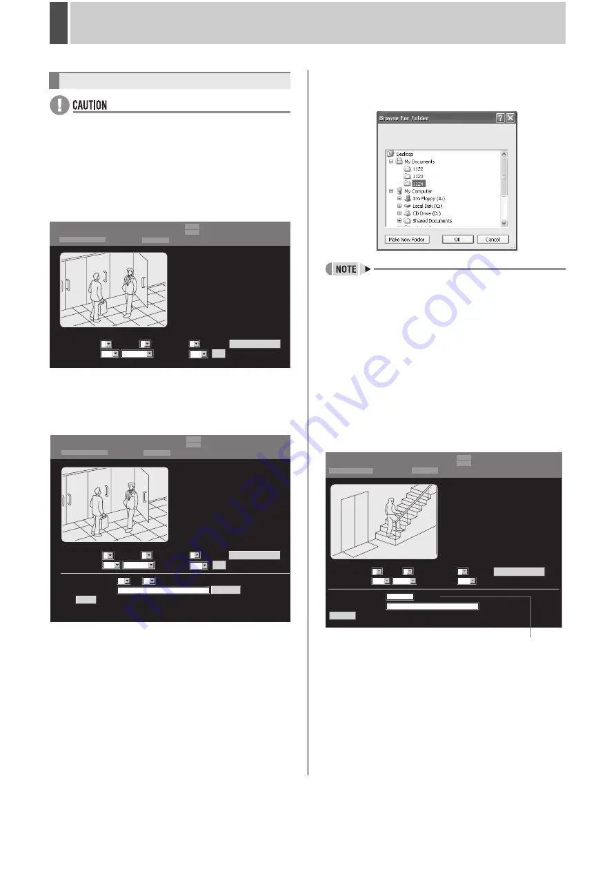
1

Displays live image for users with 

download authorization.

2

Set “SAVE TO PC” to “ON”.

3

Click [SET].

The save setting items are displayed.

4

Set “DURATION”.

Use units of one hour and one minute to set the image 
duration to save to PC.

5

Click [BROWSE].

A dialog box for selecting the save location is displayed.
Select a suitable save location.

z

Alternatively, enter the path directly into “DESTINATION 
FOLDER”.

6

Enter the save location and click the 

[OK] button.

The setting menu closes and the screen returns to the display 
for step 3 above.
The “DESTINATION FOLDER” location is displayed.

7

Click [START].

The saving process begins and the elapsed save time and 
saving screen are displayed.
The elapsed save time is incremented as the save process 
progresses.

Downloading live images to a PC

LIVE

NORMAL RECORDING MODE

01-01-07   00: 40: 32

ALARM RECORDING MODE

01

STOP
STOP

LV1:0  LV2:0


LV3:0 


LV4:1

QUALITY     


 :

3

READ INTERVAL : 

SIZE    :

AUDIO                  :

1

1

OFF

SET

SAVE TO PC : 

----

OFF

CAMERA CONTROL

USER ID ID4

DURATION                      :

DESTINATION FOLDER :

MIN

HR :

BROWSE

LIVE

NORMAL RECORDING MODE

01-01-07   00: 00: 00

ALARM RECORDING MODE

STOP
STOP

START

01

C:\

00

LV1:0  LV2:0


LV3:0 


LV4:1

QUALITY     


 :

3

READ INTERVAL : 

SIZE    :

AUDIO                  :

1

1

ON

SET

SAVE TO PC : 

----

OFF

CAMERA CONTROL

01

USER ID ID4

LIVE

NORMAL RECORDING MODE STOP

01-01-07  00: 47: 05

ALARM RECORDING MODE

DURATION                      :

DESTINATION FOLDER :

SAVE IN PROGRESS

01

/ 00:06:00

STOP

00:00:00

C:\ My documents\1124

CANCEL

LV1:0  LV2:0


LV3:0 


LV4:1

CAMERA CONTROL

QUALITY       :

READ INTERVAL :

SIZE  :

AUDIO                  :

SAVE TO PC :

3

1

1

OFF

----

ON

USER ID ID4

Elapsed save time

Summary of Contents for DSR-5709P

Page 1: ...anish and Italian INSTRUCTION MANUAL z Die BEDIENUNGSANLEITUNG in den Sprachen Deutsch Französisch Spanisch und Italienisch finden Sie auf der beiliegenden CD ROM z Utilisez le CD ROM fourni pour consulter le MANUEL D INSTRUCTIONS en allemand français espagnol et italien z Consulte en el CD ROM suministrado el MANUAL DE INSTRUCCIONES en alemán francés español e italiano z Per il MANUALE DI ISTRUZI...

Page 2: ...ce However in the event of a problem the owner is advised not to attempt to make repairs or open the cabinet Servicing should always be referred to your dealer or Sanyo Authorized Service Centre WEEE Symbol Information WARNING TO REDUCE THE RISK OF FIRE OR ELECTRIC SHOCK DO NOT EXPOSE THIS APPLIANCE TO RAIN OR OTHER MOISTURE To avoid electrical shock do not open the cabinet Refer servicing to qual...

Page 3: ...z Search by thumbnail using alarm search z Search by date time z Search within the archive area z Search for intruder motion using motion detection search Four level user level function allows restriction of users for data and equipment management JP 115 Expandable and can be connected to a PC z Connect a recordable CD drive or DVD drive VA EXD1 sold separately to enable copying of recordings to a...

Page 4: ...DEO FROM A CAMERA 22 Viewing on a full screen 22 Viewing on quad screens 23 Viewing on multi 9 or multi 16 screens 24 Enlarging video 24 Automatic camera selection 25 Viewing on monitor 2 26 3 RECORDING 29 Normal recording 29 Timer recording 29 Alarm recording 30 Pre alarm recording 30 Bookmarking video while recording 31 4 PLAY 32 Playing video on a full screen 32 Fast forward and fast rewind pla...

Page 5: ...etting data display 112 Setting for control terminal output 113 Setting the buzzer 114 Setting the security lock 115 Setting RS 485 120 Hard disk initialization and mirroring 122 Expanding Replacing and initializing the hard disk 124 Network settings 125 Making network control settings 128 5 SCREEN SET 132 Setting quad and multi 9 16 display 132 Setting the interval and monitors for automatic scre...

Page 6: ...PC 181 1 SETTINGS 183 Making menu selections 183 Menu structure 184 2 INITIAL SET 185 1 CLOCK SET 185 2 SUMMER TIME SET EXT CLOCK SET 185 3 HOLIDAY SET 186 3 RECORD SET 187 1 RECORDING AREA SET 187 2 RECORDING CONDITIONS SET 188 3 NORMAL REC MODE SET 189 4 PROGRAM REC SET 190 5 TIMER SET 191 6 ALARM REC MODE SET 192 4 GENERAL SET 195 1 DISPLAY SET 195 2 BUZZER SET 195 3 SECURITY LOCK SET 196 4 USE...

Page 7: ...ons of the Viewer Operating Panel 215 Saving and Printing Images 216 Setting the Date and Time Display Format 216 INTERFACE SPECIFICATIONS 217 RS 485 specifications 217 DVR VCR command table 218 2 INTERFACE SPECIFICATIONS 217 RS 485 specifications 217 DVR VCR command table 218 3 Specifications 219 Specifications 219 Dimensions 220 Table of recording rates and times 221 Table of recording rate sett...

Page 8: ...tion be sure to first of all pack it using the specified materials In addition choose a method of transportation that minimizes vibration Notes on installation locations Avoid subjecting the HDD to sudden impact or vibration In addition avoid using it in dusty locations or near magnetic objects The following precautions should be observed in order to prevent the loss of recorded data z Do not subj...

Page 9: ...le to replace the damper or vibration absorber as well z Cooling fan Three years The malfunction of the fan causes the temperature inside the equipment to rise which may result in the hard disk failure Important recordings z Always perform test recording in advance to confirm whether the playback of the digital video recorder is normal z Note that Sanyo accepts no responsibility for losses occurri...

Page 10: ...s to flash z If an alarm occurs The indicator for the corresponding camera starts to flash 8 FUNC button Activates dome camera operation mode The operation of other buttons changes JP 150 Use also for advanced menu functions 9 QUAD button and indicator JP 23 Displays video in quad screens The indicator lights up while in quad screen display The indicator turns off when using a different screen dis...

Page 11: ...es 20 MARK COPY button and indicator JP 53 z MARK You can bookmark any video images during recording or playback z COPY Copies recorded video onto the archive area of hard disk USB memory CD R RW disk DVD R RW disk or other media The indicator lights up during the copy process 21 SHUTTLE HOLD button and indicator JP 32 Locks shuttle dial operation for a constant speed during playback or slow playb...

Page 12: ... E X T T IM E R IN OUT A B C C 1 2 3 4 5 6 7 8 9 10 11 12 13 14 15 16 R1 R2 C RS 485 SANYO SSP RS 485 TERMINATE OFF ON 4 5 17 6 14 7 2 3 16 1 8 9 18 10 11 13 15 12 Pin Signal C Ground ALARM IN 1 Alarm input No 1 ALARM IN 2 Alarm input No 2 ALARM IN 3 Alarm input No 3 ALARM IN 4 Alarm input No 4 ALARM IN 5 Alarm input No 5 ALARM IN 6 Alarm input No 6 ALARM IN 7 Alarm input No 7 ALARM IN 8 Alarm inp...

Page 13: ... a VGA monitor to this terminal so that it obtains high resolution video output at XGA 1024 x 768 75Hz 13 MAIN MONITOR output terminal Connects to the main monitor 14 MON2 output terminal Connects to monitor 2 15 RS 485 termination switch Used when connecting multiple devices from the RS 485 control connectors 16 RS 485 control connectors A B Connects to a system controller or dome cameras 17 AC p...

Page 14: ...T VGA OUT MONITOR OUT DO NOT CONNECT TO PHONE LINE A B MAIN MON2 AUDIO 1 2 3 4 5 6 7 8 9 10 11 12 13 14 15 16 ALARM IN SENSOR ALARM OUT SELECTABLE OUTPUT 1 NON REC OUT VIDEO LOSS OUTPUT 2 ARACHIVE FULL TIMER REC OUT AC IN CONTROL 2ND RS 485 422 EXCEPT SANYO SSP REMOTE C L O C K IN C L O C K O U T A L A R M R E S E T W A R N IN G O U T F U L L A L A R M O U T P U T 1 O U T P U T 2 E X T T IM E R IN...

Page 15: ...one line A is left and B is right viewed from the back A Non inverting driver output receiver input B lnverting driver output receiver input Connection The digital video recorder supports both straight type and crossed type connection cables When using a straight type connection cable connect the RS 485 connector pin A to the pin A socket or pin B to the pin B socket When using a crossed type conn...

Page 16: ...r z Connect as shown above and set to full screen in the CAMERA CONTROL SET screen to control camera with the digital video recorder z If connected as shown above settings must be made in CAMERA CONTROL SET screen z Connect other companies cameras to the 2ND RS 485 422 terminals 1 Connect as above Connect SSP dome cameras to VIDEO IN 1 and 2 2 Set the camera numbers and protocols in the CAMERA CON...

Page 17: ...ou may use either of straight or cross type Ethernet cable To connect to an ADSL modem and other devices be sure to read the instruction manuals for each connected device Connect a microphone and speakers via an amplifier in order to input or output audio When using external alarms i e intruder sensors connect external switches to the ALARM IN terminals Only terminals 1 to 9 are available on the D...

Page 18: ... center When flashing at 4Hz Four times per second The hard disk is checked automatically when the power is turned on The POWER indicator flashing indicates that a malfunction has been found on the hard disk and the hard disk must be replaced or initialized If you need to save video stored on the disk contact a Sanyo service center When flashing at 1Hz Once per second A fan malfunction has occurre...

Page 19: ...s displayed when audio is being played back if audio is recorded 7 Alarm display and alarm count display JP 98 When an alarm is set using the ALARM REC MODE SET menu item the following information is displayed z When alarm recording is set ALARM and the alarm number are displayed in stand by mode ALARM flashes during alarm recording z When pre alarm recording is in progress PRE and the alarm numbe...

Page 20: ...the display position of the operation display area EXIT OSD 01 02 03 04 01 01 07 00 00 00 EN A1 01 01 07 00 00 00 EN A1 Operation display area Top default setting Bottom Hidden Operation display area Changing the language Item Setting Description LANGUAGE ENGLISH Sets the language to English FRANCAIS Sets the language to French DEUTSCH Sets the language to German ESPAÑOL Sets the language to Spani...

Page 21: ...ANGUAGE CLOCK SET and then turn the shuttle dial clockwise The LANGUAGE LANGUE SPRACHE IDIOMA screen is displayed LANGUAGE LANGUE SPRACHE IDIOMA ENGLISH CLOCK SET 01 01 2007 MON 00 00 00 SUMMER TIME SET MODE USE WEEK MONTH TIME ON LST SUN 03 02 00 OFF LST SUN 10 02 00 EXT CLOCK SET ADJUST TIME 01 00 LANGUAGE LANGUE SPRACHE IDIOMA ENGLISH CLOCK SET 01 01 2007 MON 00 00 00 SUMMER TIME SET MODE USE W...

Page 22: ...N LST SUN 03 02 00 OFF LST SUN 10 02 00 EXT CLOCK SET ADJUST TIME 01 00 26 01 2007 FRI 00 00 00 26 01 2007 FRI 08 30 00 EXIT OSD RECORDING AREA SET TOTAL CAPACITY 1500GB INTERNAL HDD 500GB EXTERNAL HDD 1000GB RECORDING AREA 80 AREA FULL RESET ARCHIVE AREA 20 AREA FULL RESET CAUTION WHEN THE AREA SETTING IS CHANGED THE WHOLE AREA WILL BE INITIALIZED B Archive area A Recording area Hard disk recorde...

Page 23: ... The ZOOM indicator lights up and a blue zoom frame appears in the center of the screen 2 Move the zoom frame to the area to be magnified z Turn the jog dial to move the zoom frame to the left or right z Turn the shuttle dial clockwise and then turn the jog dial to move the zoom frame vertically Move the zoom frame to the area to be magnified 3 Turn the shuttle dial clockwise The area enclosed by ...

Page 24: ...AD button The QUAD indicator lights up and video from four separate cameras is displayed simultaneously Video from Camera No 1 through Camera No 4 is initially displayed 2 To view video from other cameras press the QUAD button again Each time this button is pressed the four images on the quad screen change in order of cameras No 1 4 5 8 9 12 and 13 16 default setting On the DSR 5709P the images ch...

Page 25: ... video In addition video can also be enlarged during full screen and quad screen displays For DSR 5709P this operation is available when in multi 9 quad and full screen display Example Enlarging video during multi 9 screen display 1 Press the PLUS button during multi 9 screen display The PLUS indicator lights up and the video from one camera is enlarged 2 Press a CAMERA SELECT button The video fro...

Page 26: ...ENCE button The four images on the quad screen automatically change in order of cameras No 1 4 5 8 9 12 and 13 16 On the DSR 5709P the video changes automatically in order of cameras No 1 4 5 8 9 3 etc 3 Press the SEQUENCE button to return to normal quad screen display Automatic selection ends and the display returns to the normal quad screen Pressing the following buttons displays the respective ...

Page 27: ...u screen is being displayed search menu is being operated or camera is being controlled Example Selecting Camera 4 2 Press the No 4 CAMERA SELECT button The video from Camera No 4 is displayed in full screen on monitor 2 2 Press the QUAD button The video from cameras No 1 through 4 is displayed in quad screen on monitor 2 3 To view video from another camera press the QUAD button again Each time th...

Page 28: ...s of the quad screen on monitor 2 automatically change in order of cameras No 1 4 5 8 9 12 and 13 16 On the DSR 5709P the video changes automatically in order of cameras No 1 4 5 8 9 3 etc 4 Press the SEQUENCE or QUAD button to return to normal quad screen display Automatic selection ends and normal quad screen display returns Setting automatic full screen selection 03 06 01 09 07 08 04 01 01 07 0...

Page 29: ...2 Set MON 2 DISPLAY from the ALARM OPERATION SET screen to SWITCH LAST or FIRST JP 108 When an alarm occurs the corresponding video is displayed in full screen on monitor 2 3 Press the MON2 button to end the monitor 2 setting procedure The MON2 indicator turns off Displaying alarm video in full screen format 01 01 07 00 00 00 04 MON2 ...

Page 30: ...video recorder for the first time Recording is not possible until the time is set JP 20 1 Set timer recording JP 92 2 Press the TIMER button The TIMER indicator lights up and the digital video recorder enters timer recording standby mode z At the time specified for the start of timer recording the REC STOP indicator lights up REC i e the recording symbol appears in the operation display and record...

Page 31: ...he hard disk has remaining memory capacity Alarm recording is not performed when OFF is set z When OVERWRITE on the RECORDING CONDITIONS SET screen is set to OFF and the space remaining in the recording area becomes insufficient the FULL indicator begins to flash If recording is continued beyond this point the recording area becomes full and recording stops Perform AREA FULL RESET to enable record...

Page 32: ...ress the MARK COPY button while recording video You will see the BOOKMARK SUCCESS message and a recording point of the video marked when the button is pressed will be registered in the bookmark list z You can register up to 64 bookmarks If the maximum number is exceeded the oldest bookmark will be overwritten with a new data i e the overwriting takes place in chronological order MARK COPY button B...

Page 33: ...ounter clockwise during video playback Turn the shuttle dial to use fast forward and fast rewind playback When turned clockwise appears in the operation display and fast forward playback begins When turned counter clockwise appears in the operation display and fast rewind playback begins Fast forward and fast rewind speed increase the more the shuttle dial is turned Return the shuttle dial to cont...

Page 34: ...playback While in reverse playback turn the jog dial clockwise to use reverse slow playback is displayed in the operation display area Reverse slow playback speed decreases the more the jog dial is turned clockwise and increases as it is returned 4 Returning to normal playback Press the SHUTTLE HOLD button while the SHUTTLE HOLD indicator is lit to release the lock status is displayed in the opera...

Page 35: ...clockwise The still image is moved back by one frame or field z If normal fast forward or fast rewind playback is performed either for playback during alarm recording or for continuous playback from the normal recording area and alarm recording area the image may appear to pause in certain cases z The jog dial can be turned to increase the speed of frame advance You can bookmark any video images w...

Page 36: ...ECT button On the DSR 5709P press the CAMERA SELECT 1 9 button 1 Press the MULTI button during playback The MULTI indicator lights up and video from 16 separate cameras is displayed simultaneously Press the MULTI button again to display multi 9 screens The DSR 5709P can only display video from nine cameras 2 To return to full screen display press a CAMERA SELECT button On the DSR 5709P press the C...

Page 37: ...any single camera on nine screens in proper time sequence It is especially useful when you need to confirm the stream of video images as the function provides a series of nine images that will be refreshed in order of precedence 1 Play back video from any camera on a full screen which you want to view using flash playback 2 Press and hold for a while the CAMERA SELECT button corresponding to the n...

Page 38: ...has been stored in the archive area Search also by archive or camera number 6 MOTION DETECTION SEARCH JP 47 Search and play back video of moving objects detected by motion sensors ALARM button SEARCH button Shuttle dial Jog dial FUNC button CAMERA SELECT button Archive area Recording area SEARCH ALARM LOG SEARCH ALARM SEARCH ALARM THUMBNAIL SEARCH TIME DATE SEARCH ARCHIVE AREA SEARCH MOTION DETECT...

Page 39: ...original selected area To confirm normal recording Press the FUNC button for approximately 3 seconds to search for normal recording A blue mark is displayed at the top left of the screen and normally recorded parts are displayed in blue The search for normal recording may take some time To abort the search turn the shuttle dial counter clockwise z If MONTH is selected in step 4 above each frame re...

Page 40: ...m video was recorded 3 CH Indicates the alarm video s channel or camera number 4 TOTAL ALARMS Indicates the total number of alarm video recordings 5 SEARCH Search by specifying an alarm number JP 40 6 CHANNEL Search by specifying a camera number JP 41 7 Preview Displays the selected alarm video Setting Description ALARM The ALARM SEARCH screen JP 39 is displayed and the search results are displaye...

Page 41: ...Turn the jog dial and shuttle dial to select an alarm number Turn the shuttle dial to move through the field and turn the jog dial to select individual numbers 0 through 9 ALARM SEARCH NO DATE TIME CH TOTAL ALARMS 0000028 0000028 10 05 19 15 01 SEARCH 0000028 0000027 10 05 18 57 02 CHANNEL 0000026 10 05 18 55 03 0000025 10 05 18 52 03 0000024 10 05 22 05 01 0000023 10 05 21 59 05 0000022 10 05 21 ...

Page 42: ...000023 10 05 21 59 05 0000022 10 05 21 33 04 0000021 10 05 21 25 06 MOVE JOG SELECT SHUTTLE ALARM SEARCH NO DATE TIME CH TOTAL ALARMS 0000028 0000028 10 05 19 15 01 SEARCH 0000028 0000027 10 05 18 57 02 CHANNEL 0000026 10 05 18 55 03 0000025 10 05 18 52 03 0000024 10 05 22 05 01 0000023 10 05 21 59 05 0000022 10 05 21 33 04 0000021 10 05 21 25 06 MOVE JOG SELECT SHUTTLE FUNC 05 06 07 08 09 10 11 1...

Page 43: ...eo recorder is recording or stopped The SEARCH indicator lights up and the SEARCH screen is displayed 2 Turn the jog dial to select ALARM THUMBNAIL SEARCH and then turn the shuttle dial clockwise The nine latest alarm video thumbnails are displayed An alarm number and camera number are indicated together with each alarm recording and the number of the currently selected recording flashes To view a...

Page 44: ...on The SEARCH and CHANNEL input fields are displayed 2 Turn the shuttle dial clockwise The SEARCH input field flashes 3 Select alarm number by turning the jog dial and shuttle dial Move the unit place with the shuttle dial and select numbers 0 9 with the jog dial 4 Turn the shuttle dial clockwise The specified number alarm is searched for and thumbnails are displayed Press the FUNC button to cance...

Page 45: ...H screen is displayed 1 RECORDING TOP Indicates the date time of the earliest video recording 2 RECORDING END Indicates the date time of the most recent video recording 3 CHANNEL Input a camera number to search 4 SEARCH Input date and time to search 5 PREVIEW Select this option and turn the shuttle dial clockwise to display the preview screen 6 VIEW Select this option and turn the shuttle dial clo...

Page 46: ...d search mode The SEARCH indicator turns off 7 Turn the jog dial to select VIEW and then turn the shuttle dial clockwise The selected recording is played back on the full screen z The retrieved recording can be displayed on the full screen without displaying the preview screen by entering the date and time and then selecting VIEW z If CHANNEL is set to and playback is started the recording is disp...

Page 47: ...t or previous screen Turn the jog dial clockwise or counter clockwise accordingly z Press the ALARM button to display the next eight recordings and for the previous eight recordings z Up to eight recordings can be displayed in the ARCHIVE AREA SEARCH screen z To switch to the copy setting screen Press the MARK COPY button with a video specified in the list JP 52 z To end search mode Press the SEAR...

Page 48: ...nd then turn the shuttle dial clockwise The MOTION DETECTION SEARCH screen is displayed Entering an archive number to search for an alarm video ARCHIVE AREA SEARCH NO DATE START CH 0000001 20 10 14 15 01 SEARCH 0000028 0000002 20 10 15 15 01 CHANNEL 0000003 20 10 16 15 01 0000004 20 10 17 15 01 0000005 20 10 18 15 01 0000006 20 10 19 15 01 MOVE JOG SELECT SHUTTLE FUNC ARCHIVE AREA SEARCH NO DATE S...

Page 49: ...icator turns off 1 Turn the shuttle dial clockwise while video is being displayed on the preview screen 1 Turn the jog dial to set the start date and time for motion sensing i e 10 AM on the same day and then turn the shuttle dial clockwise The recording for the selected time is displayed in the preview screen The cursor moves to END 2 Turn the shuttle dial clockwise Setting Description ALARM Sear...

Page 50: ...as change to gray 3 Press the FUNC button turn the jog dial to select LEVEL and then turn the shuttle dial clockwise OFF flashes 4 Turn the jog dial to select sensitivity and then turn the shuttle dial clockwise After the sensitivity level is set the cursor moves to EXIT Settings indicates default setting 5 Turn the shuttle dial clockwise The display returns to the MOTION DETECTION SEARCH screen M...

Page 51: ...is recording or stopped The SEARCH indicator lights up and the SEARCH screen is displayed 2 Turn the jog dial to select BOOK MARK SEARCH and then turn the shuttle dial clockwise The BOOKMARK SEARCH screen is displayed The eight bookmarks are displayed in a list 1 NO The number of bookmark is displayed 1 up to 64 2 DATE TIME The date and time of bookmarked video is displayed 3 CH The recording came...

Page 52: ...display the next eight recordings and for the previous eight recordings z To switch to the copy setting screen Press the MARK COPY button with any video specified in the list JP 53 z To exit the search mode Press the SEARCH button The SEARCH lamp goes off BOOKMARK SEARCH NO DATE TIME CH 0000001 10 05 19 15 01 0000002 10 06 18 40 02 0000003 10 07 18 52 03 0000004 10 07 18 55 03 0000005 10 08 22 05 ...

Page 53: ...video recorder s archive area a USB memory a CD R RW or a DVD R RW Copying video to the hard disk s archive area JP 53 Copying video to a CompactFlash card or Microdrive JP 54 Copying video to a CD R RW or DVD R RW JP 57 z Copied data is stored as continuous still images z If audio is recorded audio can also be copied Archive area Copy Recording area USB USB memory Recording area USB External reco...

Page 54: ... Copying video to the hard disk s archive area MARK COPY button PLAY STOP button Shuttle dial Jog dial STILL button STILL COPY TO ARCHIVE AREA UNIT PICTURES AUDIO OFF HOW MANY 1 COPY CH 01 02 03 04 05 06 07 08 09 10 11 12 13 14 15 16 SELECT COPY CHANNEL COPY START FORMAT ERASE USB MEMORY FORMAT ERASE START MARK COPY COPY TO ARCHIVE AREA UNIT PICTURES AUDIO OFF HOW MANY 1 COPY CH 01 02 03 04 05 06 ...

Page 55: ...Press the MARK COPY button Copies video saved in recording area or archive area onto a USB memory Example Copying 20 images 1 Insert a USB memory z The digital video recorder has a USB port on the front and rear panels respectively however you can not use them at the same time Insert a USB memory in either of the front or rear port If the both ports are inserted the front port takes precedence z R...

Page 56: ...NY 1 COPY CH 01 02 03 04 05 06 07 08 09 10 11 12 13 14 15 16 SELECT COPY CHANNEL COPY START FORMAT ERASE USB MEMORY FORMAT ERASE START COPY TO USB MEMORY UNIT PICTURES AUDIO OFF HOW MANY 1 COPY CH 01 02 03 04 05 06 07 08 09 10 11 12 13 14 15 16 SELECT COPY CHANNEL COPY START FORMAT ERASE USB MEMORY FORMAT ERASE START Setting Description PICTURES The specified number of images after the specified l...

Page 57: ...layed and the cursor moves to COPY START 13 Turn the shuttle dial clockwise Copying begins The message COPY TO USB MEMORY is displayed on screen during the copy procedure When copying is completed COPY FINISHED is displayed To cancel copying Press the MARK COPY button z When a USB memory becomes full during a copy operation a message will appear before the operation stops By making any control act...

Page 58: ...ckwise ARCHIVE AREA flashes 6 Turn the jog dial to select DISC WRITER and then turn the shuttle dial clockwise The cursor moves to UNIT 7 Turn the shuttle dial clockwise PICTURES flashes Copying to a CD R RW or DVD R RW MARK COPY button PLAY STOP button Shuttle dial Jog dial STILL button USB STILL MARK COPY COPY TO ARCHIVE AREA UNIT PICTURES AUDIO OFF HOW MANY 1 COPY CH 01 02 03 04 05 06 07 08 09 ...

Page 59: ... to show the media type and free space of the copy destination The cursor is placed on NO OF COPY Setting Description PICTURES The specified number of images after the specified location are copied Specify the number of images next to HOW MANY You can set any number from 1 to 99 TIME The specified duration after the specified location is copied TIME minutes seconds Specify hours minutes second nex...

Page 60: ...ration you need to configure VALIDATE using the jog dial Once the setting is done turn the shuttle dial clockwise and the cursor moves to COPY START Settings indicates default setting z When an error is detected during disc verification you are presented with a warning message that states either VERIFY ERROR or COMPARE ERROR Chances are that your medium is defective or corrupted replace it with a ...

Page 61: ...gardless of the target medium type DVD or CD Example 3 This example illustrates how 3000MB data can be multi session written onto one DVD R with 2500MB free space CD R with 300MB free space and CD R with 500MB free space Example 4 This example illustrates how 1500MB data can be copied to 9 CD R discs 650MB each with NO OF COPY set to 3 z When you copy data across multiple discs with NO OF COPY set...

Page 62: ...cognize FAT32 CompactFlash cards Formatting a USB memory CD RW or DVD RW COPY TO ARCHIVE AREA UNIT PICTURES AUDIO OFF HOW MANY 1 COPY CH 01 02 03 04 05 06 07 08 09 10 11 12 13 14 15 16 SELECT COPY CHANNEL COPY START FORMAT ERASE USB MEMORY FORMAT ERASE START COPY TO ARCHIVE AREA UNIT PICTURES AUDIO OFF HOW MANY 1 COPY CH 01 02 03 04 05 06 07 08 09 10 11 12 13 14 15 16 SELECT COPY CHANNEL COPY STAR...

Page 63: ...s format IMG followed by a 5 digit serial number Each of these folders can contain up to 200 image files that make up the fourth layer 4 For image files with sound the corresponding WAV files are stored in the SOUND folder 5 The INFO folder is created on a session by session basis and it contains configuration information files 6 Viewer related files including AUTRUN INF IJL15 DLL J2KCOREX DLL VIE...

Page 64: ...ted and the display returns to the normal screen Basic menu operations EXIT OSD button Jog dial Shuttle dial MENU button MAIN MENU 1 INITIAL SET 2 RECORD SET 3 GENERAL SET 4 SCREEN SET 5 POWER LOSS USED TIME 6 INITIALIZATION LOG 7 COPY MENU SETTINGS 8 ADVANCED MENU SET MOVE JOG SELECT SHUTTLE MENU MAIN MENU 1 INITIAL SET 2 RECORD SET 3 GENERAL SET 4 SCREEN SET 5 POWER LOSS USED TIME 6 INITIALIZATI...

Page 65: ...hange menu settings during the suspend mode To resume video recording Press the EXIT OSD button Recording resumes under the same conditions that existed when it was suspended z While the recording is suspended the digital video recorder does not accept any new recording operation z If the menu setting file is uploaded or power supply is interrupted while recording is suspended the original recordi...

Page 66: ...ME 6 INITIALIZATION LOG 7 COPY MENU SETTINGS 8 ADVANCED MENU SET MOVE JOG SELECT SHUTTLE RECORD SET 1 NORMAL REC EASY SET 2 RECORDING AREA SET 3 RECORDING CONDITIONS SET 4 NORMAL REC MODE SET 5 PROGRAM REC SET 6 TIMER SET 7 ALARM REC MODE SET 8 ALARM OPERATION SET MOVE JOG SELECT SHUTTLE MAIN MENU Sub menus Turn the jog dial to select the setting item and then turn the shuttle dial clockwise INITI...

Page 67: ... for automatic camera selection and the switching of masking and motion sensor operations EXIT OSD button MENU button Shuttle dial Jog dial CAMERA SELECT button QUAD button MAIN MENU 1 INITIAL SET 2 RECORD SET 3 GENERAL SET 4 SCREEN SET 5 POWER LOSS USED TIME 6 INITIALIZATION LOG 7 COPY MENU SETTINGS 8 ADVANCED MENU SET MOVE JOG SELECT SHUTTLE MAIN MENU Configuration INITIAL SET 1 LANGUAGE CLOCK S...

Page 68: ...ime Settings indicates default setting Setting the language Setting the time Setting the summer time MENU LANGUAGE LANGUE SPRACHE IDIOMA ENGLISH CLOCK SET 01 01 2007 MON 00 00 00 SUMMER TIME SET MODE USE WEEK MONTH TIME ON LST SUN 03 02 00 OFF LST SUN 10 02 00 EXT CLOCK SET ADJUST TIME 01 00 Setting Description USE Time is automatically adjusted to summer time NO USE Time is not automatically adju...

Page 69: ...tting is completed and the display returns to the normal screen Use the following procedure to align the time of all digital video recorders daily when multiple recorders are connected Default setting OFF When time signal is input through the CLOCK IN terminal on the rear panel the internal clock of the digital video recorder is automatically adjusted according to the time signal z If you use this...

Page 70: ... set JP 90 All settings for programs No 1 4 are set to 1FPS for channels with cameras connected and OFF for channels with no cameras connected z Automatic screen selection time period and monitor settings JP 134 All settings for time periods T1 4 are set to 1S for channels with cameras connected and OFF for channels with no cameras connected z Setting masks JP 136 All settings for time period T1 4...

Page 71: ...monitor 2 camera title is 8 characters for multi 9 screen display and 6 characters for multi 16 screen display Example Setting the title HALL 1STFL for Camera No 3 1 Press the MENU button The MENU indicator lights up and the MAIN MENU is displayed 2 Turn the jog dial to select 1 INITIAL SET and then turn the shuttle dial clockwise The INITIAL SET screen is displayed 3 Turn the jog dial to select 3...

Page 72: ...ld be set as holidays when those dates are to have the same security as Sundays z Be sure to always switch SET to ON after completing timer settings for Sunday JP 191 Example Setting 26 October as a holiday 1 Press the MENU button The MENU indicator lights up and the MAIN MENU is displayed 2 Turn the jog dial to select 1 INITIAL SET and then turn the shuttle dial clockwise The INITIAL SET screen i...

Page 73: ...ning morning lunchtime and evening to set up automatic screen selection masking and motion sensor operations and other operations Use TIME PERIOD A and TIME PERIOD B to make operation settings For example it is possible to set TIME PERIOD A for automatic screen selection and TIME PERIOD B for the masking of monitor video using a gray pattern Example For DSR 5716P Morning to lunchtime 6 00 to 11 00...

Page 74: ...erval To do this set SEQUENCE SET from the SCREEN SET screen JP 134 Masking camera video using a gray pattern Use MASK from the SCREEN SET screen to specify which cameras are to be displayed on the monitor and which are not JP 136 Alarm recording using motion sensors Set MOTION SENSOR from the ALARM REC MODE SET screen JP 105 Operations during the specified time periods SCREEN SET 1 MULTI SCREEN N...

Page 75: ...rn the shuttle dial clockwise 00 for T 3 flashes indicating the hour 7 Use the same procedure to set the hour and minutes for T 3 and T 4 8 Use the same procedure to set the hour and minutes for T 1 to T 4 in TIME PERIOD B z Settings for T 1 through T 4 cannot be made in such a way that they extend over two days i e include midnight If 00 00 midnight must be set this should be done using T 1 Any s...

Page 76: ...ic screen selection period and monitor settings JP 134 MASK indicates mask settings JP 136 and MOTION SENSOR indicates motion sensor settings JP 105 Timer period operations settings Setting Description TIME PERIOD A Applies the setting of TIME PERIOD A TIME PERIOD B Applies the setting of TIME PERIOD B ALL DAY LONG Applies the same setting for a whole day instead of different setting for each time...

Page 77: ...FUNC button Configuration RECORD SET 1 NORMAL REC EASY SET 2 RECORDING AREA SET 3 RECORDING CONDITIONS SET 4 NORMAL REC MODE SET 5 PROGRAM REC SET 6 TIMER SET 7 ALARM REC MODE SET 8 ALARM OPERATION SET MOVE JOG SELECT SHUTTLE NORMAL REC EASY SET RECORDING DURATION BASE REC RATE BASE CAUTION CONNECT CAMERA AND SET TIME BEFORE SETUP RECORDING AREA SET TOTAL CAPACITY 1200GB INTERNAL HDD 500GB EXTERNA...

Page 78: ...e shuttle dial clockwise The RECORD SET screen is displayed 3 Turn the jog dial to select 1 NORMAL REC EASY SET and then turn the shuttle dial clockwise The NORMAL REC EASY SET screen is displayed 4 Turn the jog dial to select RECORDING DURATION BASE and then turn the shuttle dial clockwise The RECORDING DURATION BASE screen is displayed The number of detected cameras is indicated by NUMBER OF CAM...

Page 79: ...es to AUDIO RECORDING Settings indicates default setting 12 Turn the shuttle dial clockwise OFF flashes RECORDING DURATION BASE RECORDING DURATION 1 DAYS TIMER RECORDING DLY OFF START STOP PICTURE QUALITY ENHANCED AUDIO RECORDING OFF NUMBER OF CAMERAS 2 REC RATE 60 000FPS CAM RECORDING DURATION BASE RECORDING DURATION 1 DAYS TIMER RECORDING DLY OFF START STOP PICTURE QUALITY ENHANCED AUDIO RECORDI...

Page 80: ... cannot be calculated ERROR is displayed z When easy setup settings and individual settings are both set the most recent settings override previous settings z Easy setup settings cannot be used with program recording or day specific timer recording 1 Press the MENU button The MENU indicator lights up and the MAIN MENU is displayed 2 Turn the jog dial to select 2 RECORD SET and then turn the shuttl...

Page 81: ...t to ON recording rates that can be set are limited 7 Turn the shuttle dial clockwise OFF flashes 8 To activate timer operation turn the jog dial to select ON and then turn the shuttle dial clockwise The cursor moves to START REC RATE BASE REC RATE FPS CAM TIMER RECORDING DLY OFF START STOP PICTURE QUALITY ENHANCED AUDIO RECORDING OFF NUMBER OF CAMERAS 1 RECORDING DURATION DAYS REC RATE BASE REC R...

Page 82: ...g dial to select YES and then turn the shuttle dial clockwise The display returns to the NORMAL REC EASY SET screen REC RATE BASE REC RATE 25 FPS CAM TIMER RECORDING DLY ON START 08 00 STOP 20 00 PICTURE QUALITY ENHANCED AUDIO RECORDING OFF NUMBER OF CAMERAS 1 RECORDING DURATION 23 DAYS REC RATE BASE REC RATE 25 FPS CAM TIMER RECORDING DLY ON START 08 00 STOP 20 00 PICTURE QUALITY ENHANCED AUDIO R...

Page 83: ...lect 2 RECORD SET and then turn the shuttle dial clockwise The RECORD SET screen is displayed 3 Turn the jog dial to select 2 RECORDING AREA SET and then turn the shuttle dial clockwise The RECORDING AREA SET screen is displayed z When the recording area allocation is changed the hard disk is initialized and all previous recordings are deleted It is important therefore to store recorded video on a...

Page 84: ...tically set to 50 The WARNING screen is displayed A message is displayed indicating that the hard disk is to be initialized 6 Turn the jog dial to select YES z If the shuttle dial is turned clockwise with NO selected the RECORDING AREA SET screen is displayed In other words the new settings are not applied Changing recording areas A B 80 80 80 20 20 20 Archive area Hard disk recording areas Record...

Page 85: ...NG AREA SET screen is displayed 4 Turn the jog dial to select AREA FULL RESET under RECORDING AREA and then turn the shuttle dial clockwise The WARNING screen is displayed To perform AREA FULL RESET for the archive area select AREA FULL RESET under ARCHIVE AREA 5 Turn the jog dial to select YES and then turn the shuttle dial clockwise Recordings can now be made to the recording area 6 Press the EX...

Page 86: ...SET and then turn the shuttle dial clockwise The RECORD SET screen is displayed 3 Turn the jog dial to select 3 RECORDING CONDITIONS SET and then turn the shuttle dial clockwise The RECORDING CONDITIONS SET screen is displayed 4 Turn the shuttle dial clockwise ON flashes for OVERWRITE under RECORDING AREA 5 Turn the jog dial to select ON or OFF and then turn the shuttle dial clockwise The cursor m...

Page 87: ...ting and 10 11 Press the EXIT OSD button The setting is completed and the display returns to the normal screen The FULL indicator flashes when the remaining capacity for the recording areas reaches the specified percentage value When the FULL indicator flashes or the recording areas become full use overwrite permission JP 84 Setting Description MANUAL COPY Manually copy recording images JP 53 AUTO...

Page 88: ... 2 RECORD SET and then turn the shuttle dial clockwise The RECORD SET screen is displayed 3 Turn the jog dial to select 3 RECORDING CONDITIONS SET and then turn the shuttle dial clockwise The RECORDING CONDITIONS SET screen is displayed 4 Turn the jog dial to select AUTO DELETE and then turn the shuttle dial clockwise OFF flashes Setting auto deleting MENU RECORDING CONDITIONS SET RECORDING AREA O...

Page 89: ... to select 4 NORMAL REC MODE SET and then turn the shuttle dial clockwise The NORMAL REC MODE SET screen is displayed 4 Turn the shuttle dial clockwise ENHANCED flashes 5 Turn the jog dial to select the PICTURE QUALITY setting and then turn the shuttle dial clockwise The cursor moves to AUDIO RECORDING Settings indicates default setting Setting normal recording RECORDING CONDITIONS SET RECORDING A...

Page 90: ... audio and video may be out of sync in some areas 8 Turn the shuttle dial clockwise 12 5 FPS flashes 9 Turn the jog dial to select the REC RATE setting and then turn the shuttle dial clockwise The cursor moves to REC PROGRAM GROUP Default setting 12 5 FPS The allowable recording time depends on the PICTURE QUALITY setting JP 88 Settings indicates default setting Setting Description OFF Audio is no...

Page 91: ... to ON using the NORMAL REC MODE SET screen certain settings for program recording may make audio recording impossible Set more than one of the 16 channels to 1 FPS or greater to record audio On the DSR 5709P set more than one of the nine channels 1 PROGRAM Selects Program No 1 through Program No 4 2 SELECT INDIVIDUAL CAMERA RATE Sets which of the connected cameras to record from Recording rates c...

Page 92: ...ss the EXIT OSD button The setting is completed and the display returns to the normal screen PROGRAM REC SET PROGRAM P 1 SELECT INDIVIDUAL CAMERA RATE FPS 01 1 02 1 03 1 04 1 05 1 06 1 07 1 08 1 09 1 10 1 11 1 12 1 13 1 14 1 15 1 16 1 NORMAL REC 57H PROGRAM REC SET PROGRAM P 1 SELECT INDIVIDUAL CAMERA RATE FPS 01 1 02 1 03 1 04 1 05 1 06 1 07 1 08 1 09 1 10 1 11 1 12 1 13 1 14 1 15 1 16 1 NORMAL R...

Page 93: ...ours z The settings made using NORMAL REC MODE SET are used to set picture quality and audio recording for timer recording JP 88 z Ensure that start and end times are input using 24 hour notation z If the start and end times are on different days i e midnight is included a T is displayed to the left of the end time 1 Press the MENU button The MENU indicator lights up and the MAIN MENU is displayed...

Page 94: ...s that can be set are limited 9 Turn the jog dial to set the timer ON OFF and turn the shuttle dial clockwise The cursor appears in the bottom line Setting Description OFF Video from all cameras is recorded at the same rate P 1 Used when recording with Program No 1 P 2 Used when recording with Program No 2 P 3 Used when recording with Program No 3 P 4 Used when recording with Program No 4 TIMER SE...

Page 95: ...dicator lights up and the MAIN MENU is displayed 2 Turn the jog dial to select 2 RECORD SET and then turn the shuttle dial clockwise The RECORD SET screen is displayed 3 Turn the jog dial to select 6 TIMER SET and then turn the shuttle dial clockwise The TIMER SET screen is displayed 4 Press the MENU RESET button All setting items are cleared Individual reservations DLY EXT High Priority Low TIMER...

Page 96: ...e dial clockwise hour flashes 2 Turn the jog dial to select 10 hour and then turn the shuttle dial clockwise 3 Turn the jog dial to select 30 minutes and then turn the shuttle dial clockwise 6 Turn the jog dial to set the end time to and then turn the shuttle dial clockwise The DLY item on line 8 automatically changes to TUE i e the day after that set on line 7 and flashes Items that do not need t...

Page 97: ...nd of recording in response to signals received via the EXT TIMER IN terminal on the rear of the digital video recorder Example Recording at a rate of 5 FPS using the EXT TIMER IN terminal 1 Connect the signal line from the external timer to the EXT TIMER IN terminal within the rear panel control terminal block 2 Press the MENU button The MENU indicator lights up and the MAIN MENU is displayed 3 T...

Page 98: ...order enters timer recording standby mode z Press the TIMER button once again to cancel timer recording z REC is displayed in the operation display when a signal is received with a pulse width of at least 1 second via the EXT TIMER IN terminal and monitoring video is recorded in the recording area z External timer recording and normal timer recording can be combined z Connect the signal line from ...

Page 99: ...G OFF PICTURE QUALITY ENHANCED PICTURE QUALITY SET AUDIO RECORDING OFF ALARM INTERLEAVE ONLY REC RATE 12 5FPS DURATION 20SEC PRE ALARM RECORDING REC RATE FPS DURATION ALARM TRIGGER ALARM MOTION SENSOR ALARM REC MODE SET ALARM RECORDING OFF PICTURE QUALITY ENHANCED PICTURE QUALITY SET AUDIO RECORDING OFF ALARM INTERLEAVE ONLY REC RATE 12 5FPS DURATION 20SEC PRE ALARM RECORDING REC RATE FPS DURATION...

Page 100: ...p 13 is set to 1 FPS or more ALL P 1 4 Audio recording is enabled when REC RATE for any one of the program registered cameras is set to 1 FPS or more ONLY P 1 4 Audio recording is disabled z You see A Audio recoding mark displayed next to REC RATE whenever audio recording is enabled Setting Description BASIC BA Basic NORMAL NO Normal ENHANCED EN Enhanced FINE FI Fine SUPER FINE SF Super Fine INDIV...

Page 101: ...in the program recording setting receives an alarm video recording starts for all the connected cameras at a recording rate which was independently specified for each connected camera in the program z Specify a program you want to apply from P 1 to P 4 z Audio recording is available only when any one of the cameras has a recording rate of 1 FPS or more ALARM REC MODE SET ALARM RECORDING ENABLED PI...

Page 102: ...eceived on another channel while alarm recording is in progress the number of alarm increments thus they are counted as two alarms However when an additional alarm is received on the same channel the both alarms are treated as one e g an additional alarm is received on CH1 while the channel is being used for alarm recording Setting Description 5SEC 10SEC 20SEC 40SEC 1MIN 2MIN 3MIN 4MIN 5MIN 10MIN ...

Page 103: ... recording MENU ALARM REC MODE SET ALARM RECORDING ENABLED PICTURE QUALITY ENHANCED PICTURE QUALITY SET AUDIO RECORDING OFF ALARM INTERLEAVE ONLY REC RATE 12 5FPS DURATION 20SEC PRE ALARM RECORDING OFF REC RATE FPS DURATION ALARM TRIGGER ALARM MOTION SENSOR ALARM REC MODE SET ALARM RECORDING ENABLED PICTURE QUALITY ENHANCED PICTURE QUALITY SET AUDIO RECORDING OFF ALARM INTERLEAVE ONLY REC RATE 12 ...

Page 104: ...he REC STOP button to record past video The alarm number next to PRE is not updated z Pre alarm recording is performed during the period set by DURATION before an alarm occurs To play back pre alarm recordings perform alarm search using the SEARCH button JP 39 Recordings are played back at the point the alarm occurs Use the shuttle dial to begin reverse playback Setting Description 100 50 25 16 67...

Page 105: ...e setting is completed and the display returns to the normal screen Setting alarm triggers MENU ALARM REC MODE SET ALARM RECORDING OFF PICTURE QUALITY ENHANCED PICTURE QUALITY SET AUDIO RECORDING OFF ALARM INTERLEAVE ONLY REC RATE 12 5FPS DURATION 20SEC PRE ALARM RECORDING REC RATE FPS DURATION ALARM TRIGGER ALARM MOTION SENSOR ALARM REC MODE SET ALARM RECORDING ENABLED PICTURE QUALITY ENHANCED PI...

Page 106: ... select 2 RECORD SET and then turn the shuttle dial clockwise The RECORD SET screen is displayed 4 Turn the jog dial to select 7 ALARM REC MODE SET and then turn the shuttle dial clockwise The ALARM REC MODE SET screen is displayed 5 Turn the jog dial to select MOTION SENSOR and then turn the shuttle dial clockwise Setting the motion sensors CH01 T 1 LEVEL OFF MODE A 1 2 3 4 5 MENU ALARM REC MODE ...

Page 107: ...r within a range 1 Turn the jog dial to move the cursor reverse highlighting to the start position and then turn the shuttle dial clockwise 2 Turn the jog dial to select A or B and then turn the shuttle dial clockwise A or B are yellow 3 Turn the jog dial to move the cursor reverse highlighting to the end position and then turn the shuttle dial clockwise 11 Turn the jog dial to select T 1 and then...

Page 108: ...on sensing is disabled 1 to 10 Motion sensing is enabled Lower numbers correspond to higher levels of sensitivity Setting sensor modes CH01 T 1 LEVEL OFF MODE A A CH01 T 1 LEVEL OFF MODE A A CH01 T 1 LEVEL OFF MODE A A Setting Description A The motion sensor alarm is triggered when a moving object is detected in A B The motion sensor alarm is triggered when a moving object is detected in B A AND B...

Page 109: ...wing procedure to display the main monitor and monitor 2 when an alarm is detected 1 Press the MENU button The MENU indicator lights up and the MAIN MENU is displayed 2 Turn the jog dial to select 2 RECORD SET and then turn the shuttle dial clockwise The RECORD SET screen is displayed 3 Turn the jog dial to select 8 ALARM OPERATION SET and then turn the shuttle dial clockwise The ALARM OPERATION S...

Page 110: ...are treated as one provided that alarm C occurs while alarm recording is in progress for alarm A Alarm Alarm Alarm recording A Example Alarm Alarm recording C Alarm recording B CH 1 CH 2 ALARM OPERATION SET ALARM RETRIGGER ON MAIN MON DISPLAY FULL ALARM PRIORITY LAST MON 2 DISPLAY NC ALARM OPERATION SET ALARM RETRIGGER ON MAIN MON DISPLAY FULL ALARM PRIORITY LAST MON 2 DISPLAY NC Setting Descripti...

Page 111: ...ximately 3 seconds Alternatively connect a switch between the ALARM RESET terminal and C terminal the grounded terminal and turn on the switch to cancel an alarm that occurs Setting Description NC When an alarm is detected Monitor 2 does not change SWITCH When a number of alarms occur the display switches between the video from the corresponding cameras showing each for one second LAST When a numb...

Page 112: ...2 BUZZER SET 3 SECURITY LOCK SET 4 RS 485 SET 5 HDD SET 6 NETWORK SET 7 NETWORK CONTROL SET MOVE JOG SELECT SHUTTLE DISPLAY SET DATE ON QUALITY ON ALARM COUNT ON TITLE ON NO VIDEO ON CONTROL OUT OUTPUT 1 NON REC OUTPUT 2 ARCHIVE FULL TIME ON AUDIO ON ALARM TYPE ON VIDEO LOSS ON BUZZER SET ALARM OFF DISK FULL ON DISK ERROR ON LOCK WARNING ON KEY IN OFF NON REC OFF DISK TEMPERATURE ON SECURITY LOCK ...

Page 113: ... Specifies whether or not to display the VIDEO LOSS message when video signal is interrupted 9 NO VIDEO Specifies whether or not to display the NO VIDEO message for the channels with which a camera is not connected z Settings 1 to 7 are indicated in the operation display area on the monitor Example 4 Turn the shuttle dial clockwise ON flashes for DATE 5 Turn the jog dial to select ON or OFF and th...

Page 114: ...l to select OUTPUT 1 and then turn the shuttle dial clockwise You will see NON REC flash 8 Turn the jog dial to select NON REC or VODEO LOSS and then turn the shuttle dial clockwise The cursor moves to OUTPUT 2 9 Turn the shuttle dial clockwise You will see ARCHIVE FULL flash 10 Turn the jog dial to select ARCHIVE FULL or TIMER REC OUT and then turn the shuttle dial clockwise 11 Press the EXIT OSD...

Page 115: ...on is pressed 6 NON REC default setting OFF Sounds a buzzer when recording is stopped 7 DISK TEMPERATURE default setting ON Sounds a buzzer accompanied with a warning message when the temperature has exceeded a given value in the hard disk drive z Setting is invalid with the hard disk in a RAID unit z Select OFF if you use hard disks other than those designated by SANYO as this function may not pr...

Page 116: ...authorization Setting the security lock MENU SECURITY LOCK SET LOCK MODE KEY FREE ACCESS LEVEL NO OPERATION AUTHORITY NORMAL COPY LV2 3 4 CAMERA CONTROL LV2 3 4 USER ID SET LV1 LIVE LV2 PLAY LV3 REC LV4 MENU SET SECURITY LOCK SET LOCK MODE KEY FREE ACCESS LEVEL NO OPERATION AUTHORITY NORMAL COPY LV2 3 4 CAMERA CONTROL LV2 3 4 USER ID SET LV1 LIVE LV2 PLAY LV3 REC LV4 MENU SET Setting Description K...

Page 117: ...o external media and camera control privileges SECURITY LOCK SET LOCK MODE PASSWORD FREE ACCESS LEVEL NO OPERATION AUTHORITY NORMAL COPY LV2 3 4 CAMERA CONTROL LV2 3 4 USER ID SET LV1 LIVE LV2 PLAY LV3 REC LV4 MENU SET SECURITY LOCK SET LOCK MODE KEY FREE ACCESS LEVEL NO OPERATION AUTHORITY CHANGE COPY LV2 3 4 CAMERA CONTROL LV2 3 4 USER ID SET LV1 LIVE LV2 PLAY LV3 REC LV4 MENU SET SECURITY LOCK ...

Page 118: ...ial to select 3 SECURITY LOCK SET and then turn the shuttle dial clockwise The SECURITY LOCK SET screen is displayed 4 Turn the jog dial to select USER ID SET and then turn the shuttle dial clockwise The USER ID SET screen is displayed Setting Description LV2 3 4 Allows users at Level 2 or higher to control cameras from the digital video recorder LV3 4 Allows users at Level 3 or higher to control ...

Page 119: ... level z The same USER ID cannot be registered more than once 10 Use the same procedure to register other users 11 Press the EXIT OSD button The setting is completed and the display returns to the normal screen 1 With the normal monitoring screen displayed press the SHUTTLE HOLD button for approximately 3 seconds The LOCK indicator on the front panel lights up and a buzzer sounds to indicate setti...

Page 120: ...word lock is activated 1 During password lock press the SHUTTLE HOLD button for approximately 3 seconds The following screen is displayed 2 Enter the user ID and password Use the jog dial shuttle dial or CAMERA SELECT buttons to enter the characters Refer to Setting camera titles JP 70 for more details regarding how to enter characters The LOCK indicator on the front panel turns off and a buzzer s...

Page 121: ...ting and then turn the shuttle dial clockwise The cursor moves to STATUS INFO Settings indicates default setting 6 Turn the shuttle dial clockwise OFF flashes for STATUS INFO 7 Turn the jog dial to select STATUS INFO and then turn the shuttle dial clockwise The cursor moves to ALARM INFO Settings indicates default setting Setting RS 485 MENU RS 485 SET DATA SPEED 19200 STATUS INFO OFF ALARM INFO O...

Page 122: ...operation capability set this address between 001 and 008 and make camera control settings JP 150 12 Press the EXIT OSD button The setting is completed and the display returns to the normal screen Setting Description ON Alarm information is transmitted OFF Alarm information is not transmitted RS 485 SET DATA SPEED 19200 STATUS INFO OFF ALARM INFO OFF ADDRESS 001 RS 485 SET DATA SPEED 19200 STATUS ...

Page 123: ... screen Set mirroring when two hard disks are built in or when hard disk expansion has been carried out and even numbered hard disks are set When mirroring has been set the same image can be recorded to two hard disks If there is a recording error the HDD SET screen can be used to select another hard disk to read the data JP 124 When mirroring is set for hard disks of different capacities mirrorin...

Page 124: ...SET DISK 1 250GB DISK 2 250GB EX DISK 1 250GB EX DISK 2 250GB EX DISK 3 250GB EX DISK 4 250GB DISK INITIALIZE CAUTION ALL RECORDING WILL BE ERASED MIRRORING OFF PLAYBACK DRIVE HDD SET DISK 1 250GB DISK 2 250GB EX DISK 1 250GB EX DISK 2 250GB EX DISK 3 250GB EX DISK 4 250GB DISK INITIALIZE CAUTION ALL RECORDING WILL BE ERASED MIRRORING OFF PLAYBACK DRIVE HDD SET DISK 1 250GB DISK 2 250GB EX DISK 1 ...

Page 125: ...t power on the external unit first and then the digital video recorder When turning off the system power off the digital video recorder first and then shut down the external unit The HDD SET screen is displayed in the following manner when hard disk expansion is carried out for the DVR or external expansion unit To initialize a recently expanded hard disk select NEW DISK INITIALIZE To initialize a...

Page 126: ... for DHCP to set The same value is set throughout the LAN z GATEWAY Select OFF for DHCP to set When connecting from a LAN to a WAN or other differing network specify the device IP address on the LAN side z PORT Sets open port Default value is 80 z NETWORK SPEED Sets restrictions for traffic in the LAN Normally set it to NO LIMIT z DNS SET Settings relating to the Domain Name Server are performed i...

Page 127: ...Default setting 255 255 255 0 Use the same procedure for setting IP ADDRESS to set the subnet mask Set each field within the range of 0 to 255 8 Set GATEWAY Default setting 0 0 0 0 Use the same procedure for setting IP ADDRESS to set the gateway Set each field within the range of 0 to 255 MENU NETWORK SET DHCP ON IP ADDRESS 0 0 0 0 SUBNET MASK 0 0 0 0 GATEWAY 0 0 0 0 PORT 00080 NETWORK SPEED NO LI...

Page 128: ...g Description NO LIMIT Network speed No limit 1024KBPS Network speed Up to 1024KBPS 512KBPS Network speed Up to 512KBPS 256KBPS Network speed Up to 256KBPS 128KBPS Network speed Up to 128KBPS 64KBPS Network speed Up to 64KBPS NETWORK SET KEY DHCP OFF IP ADDRESS 192 168 0 1 SUBNET MASK 255 255 255 0 GATEWAY 0 0 0 0 PORT 00080 NETWORK SPEED NO LIMIT DNS SET MTU SIZE 1500 ETHERNET MAC ADDRESS 12 34 5...

Page 129: ...MENU indicator lights up and the MAIN MENU is displayed 2 Turn the jog dial to select 3 GENERAL SET and then turn the shuttle dial clockwise The GENERAL SET screen is displayed 3 Turn the jog dial to select 7 NETWORK CONTROL SET and then turn the shuttle dial clockwise The NETWORK CONTROL SET screen is displayed 4 Turn the shuttle dial clockwise ON flashes for NETWORK CONTROL EXIT OSD Making netwo...

Page 130: ... NETWORK CONTROL is not displayed on the monitor connected to the digital video recorder even during network connection NETWORK CONTROL SET NETWORK CONTROL ON NETWORK STATUS ON PICTURE QUALITY ENHANCED OPERATION AUTHORITY NORMAL COPY DOWNLOAD LV3 4 CAMERA CONTROL LV2 3 4 USER ID SET LV1 LIVE LV2 PLAY LV3 REC LV4 MENU SET NETWORK CONTROL SET NETWORK CONTROL ON NETWORK STATUS ON PICTURE QUALITY ENHA...

Page 131: ...CONTROL Setting Description NORMAL User privileges remain at the default setting CHANGE Changes live image downloading privileges and camera control privileges NETWORK CONTROL SET NETWORK CONTROL ON NETWORK STATUS ON PICTURE QUALITY ENHANCED OPERATION AUTHORITY CHANGE COPY DOWNLOAD LV3 4 CAMERA CONTROL LV2 3 4 USER ID SET LV1 LIVE LV2 PLAY LV3 REC LV4 MENU SET NETWORK CONTROL SET NETWORK CONTROL O...

Page 132: ...s Setting user JP 117 from Security lock settings Change NETWORK CONTROL user ID password and level settings described on this page to change the values in the USER ID SET screen of SECURITY LOCK SETTINGS Setting Description LV2 3 4 Allows users at Level 2 or higher to control cameras from the digital video recorder LV3 4 Allows users at Level 3 or higher to control cameras from the digital video ...

Page 133: ...lt setting 5 Turn the shuttle dial clockwise The QUAD POSITION SET screen is displayed MAIN MENU 1 INITIAL SET 2 RECORD SET 3 GENERAL SET 4 SCREEN SET 5 POWER LOSS USED TIME 6 INITIALIZATION LOG 7 COPY MENU SETTINGS 8 ADVANCED MENU SET MOVE JOG SELECT SHUTTLE Main Menu EXIT OSD button Jog dial MENU button Shuttle dial Setting quad and multi 9 16 display Setting multiple screen positions 06 05 08 0...

Page 134: ...kwise to return to the QUAD POSITION SET screen 10 Press the EXIT OSD button The setting is completed and the display returns to the normal screen MAIN MON KEY QUAD1 QUAD2 QUAD3 QUAD4 MON 2 QUAD1 QUAD2 QUAD3 QUAD4 CHECK THE MAIN MON SCREEN CHECK THE MON 2 SCREEN 01 02 03 04 05 06 07 08 09 10 11 12 13 14 15 16 01 02 03 04 05 06 07 08 09 10 11 12 13 14 15 16 MAIN MON QUAD1 QUAD2 QUAD3 QUAD4 MON 2 QU...

Page 135: ... on the main monitor and monitor 2 To set the interval for each camera when displaying video at full screen select INDIV in step 4 and then go to MAIN MON 2 MONITOR SET z The interval can be set anywhere between 1 and 30 seconds 6 Press the EXIT OSD button The setting is completed and the display returns to the normal screen Example Setting the display interval of each camera s video for the main ...

Page 136: ...SITION SET 2 SEQUENCE SET FULL 1S QUAD 1S MAIN MON 2 MONITOR SET 3 MASK OFF MASK SET 4 COLOR LEVEL SET SCREEN SET 1 MULTI SCREEN NORMAL QUAD POSITION SET MULTI 9 POSITION SET MULTI 16 POSITION SET 2 SEQUENCE SET FULL 5S QUAD 1S MAIN MON 2 MONITOR SET 3 MASK OFF MASK SET 4 COLOR LEVEL SET MAIN MON 2 MONITOR SET TIME PERIOD T 1 09 00 12 00 CH 01 02 03 04 05 06 07 08 MAIN MON 1S 1S 1S 1S 1S 1S 1S 1S ...

Page 137: ...onitor screen Example Preventing the display of specific camera video at a set period as indicated by TIME PERIOD A and TIME PERIOD B 1 Make timer settings for TIME PERIOD A and TIME PERIOD B on the TIME PERIOD SET screen JP 74 Specify TIME PERIOD A and TIME PERIOD B 2 Press the MENU button The MENU indicator lights up and the MAIN MENU is displayed 3 Turn the jog dial to select 4 SCREEN SET and t...

Page 138: ...OFF OFF MON 2 OFF OFF OFF OFF OFF OFF OFF OFF NETWORK OFF OFF OFF OFF OFF OFF OFF OFF CH 09 10 11 12 13 14 15 16 MAIN MON OFF OFF OFF OFF OFF OFF OFF OFF MON 2 OFF OFF OFF OFF OFF OFF OFF OFF NETWORK OFF OFF OFF OFF OFF OFF OFF OFF MASK SET TIME PERIOD T 1 09 00 12 00 CH 01 02 03 04 05 06 07 08 MAIN MON OFF OFF OFF OFF OFF OFF OFF OFF MON 2 OFF OFF OFF OFF OFF OFF OFF OFF NETWORK OFF OFF OFF OFF O...

Page 139: ... The MENU indicator lights up and the MAIN MENU is displayed 2 Turn the jog dial to select 4 SCREEN SET and then turn the shuttle dial clockwise The SCREEN SET screen is displayed 3 Turn the jog dial to select 4 COLOR LEVEL SET and then turn the shuttle dial clockwise The COLOR LEVEL SET screen is displayed 4 Press the CAMERA SELECT button for the camera whose color level is to be set and then tur...

Page 140: ... usage duration is displayed 2 DISK 2 USE The hard disk 2 power usage duration is displayed If there is only one hard disk is displayed 3 POWER Displays the total amount of power on time for the digital video recorder 4 F W Displays the firmware version 5 EX DISK1 EX DISK2 EX DISK3 EX DISK4 USE POWER Total usage time is shown for each hard disk when expanded z Press the MENU RESET button to clear ...

Page 141: ... resetting 2 AREA Displays the recording of the target area of initialization or area resetting z ALL z RECORD z ARCHIVE 3 ACTION Displays whether initialization JP 122 or AREA FULL RESET JP 84 was selected z INITI z RESET 4 USER ID Displays the user ID of the user that performed initialization and area resetting z INITI is displayed when recording areas are changed 3 Press the EXIT OSD button The...

Page 142: ...layed 3 Turn the jog dial to select SAVE MENUS TO USB MEMORY and then turn the shuttle dial clockwise The WARNING screen is displayed 4 Turn the jog dial to select YES and then turn the shuttle dial clockwise The saving process begins When this is completed SAVING FINISHED is displayed A file named MENUCOPY BIN is created in the USB memory directory MAIN MENU 1 INITIAL SET 2 RECORD SET 3 GENERAL S...

Page 143: ...he jog dial to select 7 COPY MENU SETTINGS and then turn the shuttle dial clockwise The COPY MENU SETTINGS screen is displayed 3 Turn the jog dial to select COPY USER ID SETTINGS and then turn the shuttle dial clockwise NO flashes 4 Turn the jog dial to select NO or YES and then turn the shuttle dial clockwise 5 Turn the jog dial to select LOAD MENUS FROM USB MEMORY and then turn the shuttle dial ...

Page 144: ...d the display returns to the previous screen Copying the recording area settings MENU COPY MENU SETTINGS DVR TYPE VER SA16 00 02 SAVE MENUS TO USB MEMORY LOAD MENUS FROM USB MEMORY COPY USER ID SETTIGS NO COPY RECORDING AREA SETTINGS NO IF YOU CHOOSE YES FOR AREA SETTINGS HARD DISK WILL BE INITIALIZED COPY MENU SETTINGS DVR TYPE VER SA16 00 02 SAVE MENUS TO USB MEMORY LOAD MENUS FROM USB MEMORY CO...

Page 145: ... 4 TIME ZONE NTP SET JP 154 Use the Internet or an NTP server on a LAN to synchronize the time EXIT OSD button Jog dial Shuttle dial MENU button FUNC button MAIN MENU 1 INITIAL SET 2 RECORD SET 3 GENERAL SET 4 SCREEN SET 5 POWER LOSS USED TIME 6 INITIALIZATION LOG 7 COPY MENU SETTINGS 8 ADVANCED MENU SET MOVE JOG SELECT SHUTTLE Main Menu Configuration ADVANCED MENU SET 1 ROI SET 2 ALARM NOTICE SET...

Page 146: ... previous row are prioritized 1 Press the MENU button The MENU indicator lights up and the MAIN MENU is displayed 2 Turn the jog dial to select 8 ADVANCED MENU SET and then turn the shuttle dial clockwise The ADVANCED MENU SET screen is displayed 3 Turn the jog dial to select 1 ROI SET and then turn the shuttle dial clockwise The ROI SET screen is displayed 4 Turn the shuttle dial clockwise The ca...

Page 147: ...ption MIN Lowest quality LOW Low quality OFF Normal Same picture quality as outside ROI area HIGH Fine MAX Best quality ROI SET CH 01 QUALITY STATIC AREA 1 MIN STATIC AREA 2 OFF STATIC AREA 3 OFF EFFECTIVE REC MODE NORMAL REC AREA SET ROI SET CH 01 QUALITY STATIC AREA 1 MIN STATIC AREA 2 LOW STATIC AREA 3 HIGH EFFECTIVE REC MODE NORMAL REC AREA SET ROI SET CH 01 QUALITY STATIC AREA 1 MIN STATIC AR...

Page 148: ...to move the cursor the orange to the lower right of the position where an area is to be set and then turn the shuttle dial clockwise The cursor the orange moves to the top left of frame 2 Turn the jog dial to move the cursor to the left or right Press the FUNC button and turn the jog dial to move the cursor up or down 15 Set the areas in frame 2 and frame 3 in the same way The cursor moves to T 1 ...

Page 149: ...areas z The AREA SET screen displays an image in the recording mode configured in EFFECTIVE REC MODE When it is set to NORMAL ALARM the screen displays an image in normal recording mode z You cannot check the picture quality on the AREA SET screen while recording is in progress or prealarm recording is in effect Confirming picture quality of ROI setting CH 01 2 1 3 AREA SET screen Your new picture...

Page 150: ...DDRESS Displays the SMTP server address 3 USER MAIL ADDRESS Displays the e mail address from which the alarm notification is sent 4 SEND MAIL ADDRESS SET Displays the SEND MAIL ADDRESS SET screen J step 4 5 SUBJECT Displays the e mail subject 6 AUTHENTICATION Displays whether or not user authentication is performed 7 POP3 SERVER ADDRESS Displays the POP3 server address 8 USER ID Displays the user ...

Page 151: ...ERA CONTROL SET screen is displayed 4 Turn the jog dial to select 1 PROTOCOL ADDRESS SET and then turn the shuttle dial clockwise The PROTOCOL ADDRESS SET screen is displayed 5 Turn the jog dial to select the camera number corresponding to a connected dome camera and then turn the shuttle dial clockwise OFF flashes for PROTOCOL On the DSR 5709P cameras No 01 09 are displayed 6 Turn the jog dial to...

Page 152: ...from a VSP 9000 controller 10 Once the settings are completed on the PROTOCOL ADDRESS SET screen turn the jog shuttle counter clockwise The display returns to the CAMERA CONTROL SET screen PROTOCOL ADDRESS SET CH PROTOCOL ADD CH PROTOCOL ADD 01 SANYO RS 485 001 09 OFF 02 BBV COAX 10 OFF 03 PELCO COAX 11 OFF 04 2ND RS 485 422 004 12 OFF 05 OFF 13 OFF 06 OFF 14 OFF 07 OFF 15 OFF 08 OFF 16 OFF 2ND RS...

Page 153: ...ION field Settings indicates default setting z For PRESET you can set PRESET2 9 with DSR 5709P and PRESET2 16 with DSR 5716P z In the case more than one camera has issued an alarm simultaneously some or all trigger actions may fail to operate correctly because only one camera can be operated at a time z Actually available actions depend on each camera For more information refer to the camera s ins...

Page 154: ...1 Press the FUNC button The FUNC indicator lights up and camera operation mode is activated 2 Click the buttons to operate the camera How to Register Preset Positions 3 2 1 Operating the camera with the digital video recorder Button Button name in normal mode Operation MENU button MENU button Displays the camera menu screen ENTER button EXIT OSD button Determines items on the camera menu screen PR...

Page 155: ...net or an NTP server on a LAN 1 Press the MENU button The MENU indicator lights up and the MAIN MENU is displayed 2 Turn the jog dial to select 8 ADVANCED MENU SET and then turn the shuttle dial clockwise The ADVANCED MENU SET screen is displayed 3 Turn the jog dial to select 5 TIME ZONE NTP SET and then turn the shuttle dial clockwise The TIME ZONE SET NTP SET screen is displayed 4 Turn the shutt...

Page 156: ... Berlin Rome Greenwich Mean Time 1 hour Amsterdam Berlin Rome GMT 02 Athens Istanbul Minsk Greenwich Mean Time 2 hours Athens Istanbul Minsk GMT 03 Moscow Baghdad Riyadh Greenwich Mean Time 3 hours Moscow Baghdad Riyadh GMT 03 30 Tehran Greenwich Mean Time 3 hours 30 minutes Tehran GMT 04 Kabul Baku Tbilisi Greenwich Mean Time 4 hours Kabul Baku Tbilisi GMT 05 Islamabad Tashkent Greenwich Mean Tim...

Page 157: ... 30 40 or 50 Example 10 30 1 Turn the jog dial to select 10 and then turn the shuttle dial clockwise 00 minutes flashes 2 Turn the jog dial to select 30 and then turn the shuttle dial clockwise Default setting 01 00 Time is updated at 1 AM 11 Press the EXIT OSD button The setting is completed and the display returns to the normal screen TIME ZONE SET TIME ZONE GMT Dublin Lisbon London NTP SET SYNC...

Page 158: ......

Page 159: ...Manual for Remote Operation by Network Connection ...

Page 160: ...er for details z When controlling the digital video recorder by computer over the Internet or LAN network settings such as IP address settings are necessary See P 125 for more setting details z When a pre existing network is being used a check must be carried out by that network s administrator to confirm that the set IP addresses do not coincide with other IP addresses already in use z The dedica...

Page 161: ...m the Internet Explorer Tools menu The Internet Options window is displayed Example Windows XP 2 Click the Security tab The Security screen is displayed 3 Click Custom Level The Security Settings window is displayed Confirm that Run ActiveX controls and plug ins is set to Enable If this is not the case click Enable for Run ActiveX controls and plug ins to configure this setting as shown below This...

Page 162: ...erties from the pop up menu The General tab in the Local Area Connection Properties window is displayed 4 Check that Internet Protocol TCP IP is selected in the list of components used by the Ethernet board displayed in the This connection uses the following items box If Internet Protocol TCP IP is not selected select it 5 Click Properties The General tab in the Internet Protocol TCP IP Properties...

Page 163: ...e IP address in the URL Contact the network administrator for more details Depending on the device Port forwarding may be called Static IP Masquerade Address translation Port mapping or Virtual server z In the network settings JP 125 if a value other than 80 is set as the default port value enter a colon and then the port number after the IP address For example if the port number was set as 60001 ...

Page 164: ...ation screen of the PC The connection is cancelled and control rights are returned to the unit z To forcibly cancel PC access from the unit press and hold the SHUTTLE HOLD button for at least 3 seconds z Access from the PC is not permitted for a period of 10 seconds after access is cancelled z The access connection is also cancelled and control rights then switch back to the unit whenever communic...

Page 165: ...twork z User ID and password are changed while LV1 or LV2 user is connected to the network When network settings are changed This screen is displayed in the following cases z Settings on the DVR unit are changed z Own User ID settings are changed When connection to the network cannot be made because the DVR is being operated This screen is displayed in the following cases z Copying is made on the ...

Page 166: ... recorded images 12 Previous image LV2 3 4 Moves a still image back one frame 13 Still LV2 3 4 Pauses the image during playback 14 Next image LV2 3 4 Advances a still image forward one frame 15 Search LV2 3 4 Displays the search screen i e setting screen 16 Copy by setting Displays the copy screen i e setting screen 17 Download by setting Displays the download screen i e setting screen 18 Record L...

Page 167: ...yed z When AUDIO is set to ON or when saving real time to PC the CAMERA CONTROL button is not displayed 2 Click each button to use a dome camera 1 Channel number Displays the channel number selected using Channel selection The DSR 5709P displays only nine channels 2 Channel selection Select a camera channel The DSR 5709P displays only nine channels 3 Pan tilt Adjust camera direction Follow the cha...

Page 168: ...UR saved on the camera Press a different operation button to switch to that operation 15 Preset access Move camera into position set with preset number For preset numbers after 9 select from the drop down list and click GO 16 Preset register Select a preset number from the drop down list and click Menu set to register the current camera position 17 Record LV3 LV4 This button starts normal recordin...

Page 169: ...click the button on the operation panel while TIMER STANDBY is displayed When an alarm is detected via the ALARM IN terminal or a motion sensor the recording of alarm images starts automatically Use the alarm recording settings JP 192 to activate alarm recording or set the alarm recording not to be performed during timer recording 1 Set the conditions for ALARM RECORDING using the ALARM REC MODE S...

Page 170: ...n again Multi 16 screen display is restored To activate full screen display click on the image or click the CHANNEL button z Video from each screen of the multi screen display is updated at a speed appropriate for its channel The updating speed is affected by network conditions Switching to live images during playback Playing back recorded images Image specification Playback method When no images ...

Page 171: ...utton Playback pauses on the current image To return to normal play mode click the button while playback is paused While playback is paused click the or button Advances a frame in the forward direction Advances a frame in the reverse direction During playback click the or button The previous or next alarm image is displayed accordingly Skips to the next alarm video Skips to the previous alarm vide...

Page 172: ... to ensure that there are no playback interruptions The playback audio is delayed when compared with the originally recorded sound The following set amounts of time indicate the delay Settings indicates default setting PLAY NORMAL RECORDING MODE STOP STOP ALARM RECORDING MODE ALARM RECORDING MODE PLAYBACK AREA NORMAL 01 01 07 00 36 20 A PLAY SPEED READ INTERVAL SIZE 01 AUDIO 1 1 OFF SET SAVE TO PC...

Page 173: ...ording time 8 NORMAL RECORDING MODE Displays the current status for normal recording z STOP z RECORDING z TIMER STANDBY z TIMER RECORDING z AREA FULL in recording area 9 ALARM RECORDING MODE Displays the current status for alarm recording z STOP z PRE ALARM RECORDING z ALARM RECORDING z AREA FULL When recording area is full or automatic alarm copying is being performed and the archive area becomes...

Page 174: ...ve The DESTINATION FOLDER location is displayed 7 Click START The saving process begins and the elapsed save time and saving screen are displayed The elapsed save time is incremented as the save process progresses Downloading live images to a PC LIVE NORMAL RECORDING MODE 01 01 07 00 40 32 ALARM RECORDING MODE 01 STOP STOP LV1 0 LV2 0 LV3 0 LV4 1 QUALITY 3 READ INTERVAL SIZE AUDIO 1 1 OFF SET SAVE...

Page 175: ...1 The folder DVR00001 is created 2 Within this folder folders are created in order beginning with IMG00001 Images are stored in each folder LIVE NORMAL RECORDING MODE STOP 01 01 07 00 47 05 ALARM RECORDING MODE DURATION DESTINATION FOLDER SAVE IN PROGRESS 01 00 06 00 STOP 00 00 00 C My documents 1124 CANCEL LV1 0 LV2 0 LV3 0 LV4 1 CAMERA CONTROL QUALITY READ INTERVAL SIZE AUDIO SAVE TO PC 3 1 1 OF...

Page 176: ...data Basic operation SEARCH 1 ALARM LOG SEARCH 2 ALARM SEARCH 3 ALARM THUMBNAIL SEARCH 4 TIME DATE SEARCH 5 ARCHIVE AREASEARCH 6 MOTION DETECTION SEARCH Search menu Search mode Type of recording searched Description 1 ALARM LOG SEARCH Alarm recording Search for alarm video by specifying the date time When the search is completed images can be selected from ALARM SEARCH or ALARM THUMBNAIL SEARCH an...

Page 177: ... represents one day If WEEK is selected four frames represent one day If DAY is selected each frame represents one hour If HOUR is selected each frame represents two minutes z Click the BACK or NEXT button to shift the display one page A search is started and when it is finished the frame color changes in the following fashion Black No recordings Red Alarm recording 4 Set SEARCH to the desired sea...

Page 178: ...yback starts from the point at which the alarm was triggered All of the alarm images stored in the alarm recording area are displayed as thumbnails small images Accordingly you can search and play back alarm images using their thumbnails 1 PAGE Displays the previous and next 9 thumbnails 2 SEARCH Search by the alarm number 3 CHANNEL Search by the camera number 1 Click 3 ALARM THUMBNAIL SEARCH on t...

Page 179: ... capacity 6 CAPACITY Used archive area capacity 7 SEARCH Enter number to display as list 8 CHANNEL Enter camera number to display as list 9 SEARCH button Search using the conditions from 7 and 8 display as list 10 PREVIEW NO Current number being previewed 11 Preview image Click to start playback 1 Click 5 ARCHIVE AREA SEARCH on the SEARCH screen The ARCHIVE AREA SEARCH screen is displayed This scr...

Page 180: ...rch range by making date and time settings z The search results are displayed in a message box when SET is clicked 5 Set motion sensor detection conditions z Motion sensor positions The motion sensor setting screen displays an 8 x 10 height x width grid of sensors When one of these sensors is clicked the corresponding sensor setting mark changes to red If the same location in the grid is clicked a...

Page 181: ...k 2 PLAYBACK AREA Type of video recording that is being played back z ALARM z PRE ALARM z NORMAL z ARCHIVE 3 MESSAGE Displays a message when starting copy Example PLEASE WAIT 4 UNIT Select a method to specify copy range number of pictures time and events 5 AUDIO Specify whether or not to copy audio 6 PICTURES 1 40000 Specify the number of sheets when PICTURES is specified in UNIT 7 TIME Specify ho...

Page 182: ...T Select a method to specify copy range number of copies time number of events 5 AUDIO Select whether or not to download audio 6 PICTURES 1 40000 Enter number of images when PICTURES is specified in UNIT 7 TIME Enter time hrs min sec when TIME is specified in UNIT 8 EVNETS Specify the number of events when EVENT is specified for UNIT 9 COPY CH Select a channel to copy 10 DESTINATION FOLDER Specify...

Page 183: ...en is when TIME is set 10 When download is completed The result of download is displayed on the dialog box To return to live display click the LIVE button on the dialog box Setting Description PICTURES Specify the number of images for download number TIME Specify the time hrs min sec for download number EVENTS Specify download range with the number of events Setting Description ON Also download au...

Page 184: ...value 4 Make the required settings 5 Click the button on the operation panel The setting procedure is ended and the display returns to the normal screen monitoring image z Menu screens are not displayed during playback To display a menu stop playback return to live mode and then click the button on the operation panel z You must be connected with user level 4 LV4 to modify settings z It is not pos...

Page 185: ... z COPY z CAMERA CONTROL P 196 4 USER ID SET z USER ID z PASSWORD z LV P 197 5 RS 485 SET z DATA SPEED z STATUS INFO z ALARM INFO z ADDRESS P 198 6 HDD SET z DISK1 z DISK2 z EX DISK1 z EX DISK2 z EX DISK3 z EX DISK4 z MIRRORING z PLAYBACK DRIVE P 198 7 NETWORK SET z DHCP z IP ADDRESS z SUBNET MASK z GATEWAY z PORT z NETWORK SPEED z DNS SERVER PRIMARY SECONDARY z HOST NAME z DOMAIN SUFFIX z MTU SIZ...

Page 186: ...ation panel The MAIN MENU is displayed 2 Click 1 INITIAL SET The INITIAL SET screen is displayed 3 Click 2 SUMMER TIME SET EXT CLOCK SET The SUMMER TIME SET EXT CLOCK SET screen is displayed 4 Set MODE to USE Settings indicates default setting 5 For ON set the date time at which to switch from standard time to summer time 6 For OFF set the date time at which to switch from summer time to standard ...

Page 187: ...dure to set specific days as holidays When a day is specified as a holiday timer recording for that day is performed as if it were a Sunday Dates such as national holidays and company holidays can be set as holidays when you want those dates to have the same security as Sundays 1 Click the button on the operation panel The MAIN MENU is displayed 2 Click 1 INITIAL SET The INITIAL SET screen is disp...

Page 188: ... to overwrite from the beginning of each area Jstep 4 Reset is not required in the following cases and therefore AREA FULL RESET is not displayed z When the overwrite setting is ON 1 RECORDING AREA SET Recording area Recording mode Recording method Recording area Normal recording Manual Recording is performed by manual operation of the button on the operation panel Timer recording Automatic Record...

Page 189: ...VERWRITE for the RECORDING AREA to ON or OFF Settings indicates default setting When the overwrite setting for a recording area is OFF the unit can issue a warning as soon as the remaining space reaches a specific level JP 195 Use the following procedure to set the level at which the warning is issued 5 Set REMAINING DISK WARNING to the desired remaining space warning level Settings indicates defa...

Page 190: ...recording is performed at 25 FPS even if 50 or 100 FPS are set z When two or more cameras are connected and 50 or 100 FPS is set the actual recording rate is roughly the recording rate divided by the number of cameras Example When 8 cameras are connected and the recording rate setting is 100 FPS the actual recording rate is 12 5 FPS z When mirroring or pre alarm recording is set to ON recording ra...

Page 191: ...OGRAM REC SET The PROGRAM REC SET screen is displayed 4 Set PROGRAM to the desired program group Settings 5 For SELECT INDIVIDUAL CAMERA RATE FPS set the recording rate for each camera Set the recording rate for the cameras from which video is to be recorded Settings indicates default setting z For program recording set recording rate per channel Recording rates that can be set per channel are aut...

Page 192: ...settings z If DLY is set for any other day all rows use this setting 5 Click SAVE The setting is saved Performing timer recording Click the button on the operation panel JP 165 Overlapping of timer reservation times z If timer settings overlap recording is performed in the following priority order Individual reservations DLY EXT High Priority Low z If a reservation for a particular day or a daily ...

Page 193: ...iption OFF Alarm recording is disabled ENABLED Alarm recording is always performed regardless of timer recording or timer settings AL REC ON TIMER Alarm recording is performed only during timer recording AL REC OFF TIMER Alarm recording is performed only during recording other than timer recording OLY AL RC ON TMR Alarm recording is performed only in the period set for timer recording without time...

Page 194: ...etting is 50 FPS the actual recording rate is 12 5 FPS 9 Set DURATION to the desired alarm recording duration Settings indicates default setting Setting audio recording Setting Description OFF Audio is not recorded ON Audio is recorded Setting the alarm interleave Setting Description ONLY Video is recorded only from cameras with an alarm occurring SW Recording is switched between video from a came...

Page 195: ...als which function as operation conditions for alarm recording 13 Set ALARM TRIGGER to the desired launch signal for alarm recording Settings indicates default setting z External alarm detection This is used to describe input of an external detection signal from a door switch or the like to the unit s ALARM IN terminal z Motion sensor detection This refers to detection of motion on the monitor in ...

Page 196: ...yback 5 ALARM COUNT ON Displays the number of recorded alarms 6 ALARM TYPE ON Displays the alarm recording type z For alarm recording ALARM is displayed z For pre alarm recording PRE is displayed 7 TITLE ON Displays the camera title GENERAL SET 1 DISPLAY SET 2 BUZZER SET 3 SECURITY LOCK SET 4 USER ID SET 5 RS 485 SET 6 HDD SET 7 NETWORK SET 8 NETWORK CONTROL SET DISPLAY SET DATE ON TIME ON QUALITY...

Page 197: ...when an alarm occurs It does not sound for errors such as disk full warning disk error or recording stop To cancel the buzzer setting on the PC z Delete the folder or file created in the above mentioned process change the name of the audio file or move it to a different location on the hard disk z Press the Stop button on the PLAYBACK area on the operation panel to stop the buzzer on the PC User l...

Page 198: ...yed 2 Click 3 GENERAL SET The GENERAL SET screen is displayed 3 Click 4 USER ID SET The USER ID SET screen is displayed 4 Set user ID for USER ID 5 Set PASSWORD 6 Set user level for LV Settings 7 Click SAVE The setting is saved z The LV setting registered on line 1 cannot be changed from 4 To change the level register a separate user on a different line 4 USER ID SET Level Operation privilege LV1 ...

Page 199: ...recorded to both hard disks in a process known as mirroring Even if a problem occurs in the writing of video data to one of the disks it is possible to extract normal data from the other disk when this function is turned on 3 PLAYBACK DRIVE This item indicates which of the hard drives is used to provide video for playback when mirroring is turned on 5 RS 485 SET Item Description 1 DATA SPEED Displ...

Page 200: ...0 0 0 0 0 0 0 1 2 3 4 6 10 5 5 7 8 9 11 Item Description 1 DHCP Set from the digital video recorder whether the IP address is automatically acquired from the DHCP server or manually set Set ON when using an IP address acquired automatically from an Internet service provider or a DHCP server on a LAN and set OFF when using a fixed IP 2 IP ADDRESS Select OFF for DHCP to set Generally a private IP ad...

Page 201: ...lick the button on the operation panel The MAIN MENU is displayed 2 Click 3 GENERAL SET The GENERAL SET screen is displayed 3 Click 8 NETWORK CONTROL SET The NETWORK CONTROL SET screen is displayed 4 Set NETWORK STATUS to ON or OFF Settings indicates default setting 8 NETWORK CONTROL SET Setting Description ON During network connection the message NETWORK CONTROL is displayed on the monitor connec...

Page 202: ...THORITY is set to CHANGE set the level for CAMERA CONTROL Settings indicates default setting 9 Click SAVE The settings are saved Setting Description BACIC BA Basic picture quality NORMAL NO Normal picture quality ENHANCED EN Enhanced picture quality FINE FI Fine picture quality SUPER FINE SF Super fine picture quality Setting Description NORMAL User privileges remain at the default setting CHANGE ...

Page 203: ...T1 through T4 changes to that of TIME PERIOD A or TIME PERIOD B on the TIME PERIOD SET screen JP 74 z If the time period is set to ALL DAY LONG the display is fixed to T 1 00 00 24 00 4 Select the switching interval for each camera on the main monitor On the DSR 5709P cameras No 01 09 are displayed 5 Select the switching interval for each camera on monitor 2 On the DSR 5709P cameras No 01 09 are d...

Page 204: ...g with LV2 LV3 and LV4 are able to display all channels 2 MASK SET Item Description 1 MASK Turns masking on or off 2 TIME PERIOD Select a time period from T1 to T4 If time period is set to ALL DAY LONG on the digital video recorder the display is fixed to T 1 00 00 24 00 3 CH Turns masking on or off for each channel on the main monitor monitor 2 and network video MASK SET MASK TIME PERIOD SAVE OFF...

Page 205: ...on the operation panel The MAIN MENU is displayed 2 Click 5 POWER LOSS USED TIME The POWER LOSS USED TIME screen is displayed z The maximum number of power losses displayed is 999 1 POWER LOSS USED TIME Item Description 1 POWER Displays the number of power losses 007 and the date and time of occurrence and recovery for the eight most recent power losses 2 INTERNAL HDD Displays the power usage dura...

Page 206: ...resetting are displayed INITIALIZATION LOG Item Description 1 DATE Displays the date of initialization and area resetting 2 TIME Displays the time of initialization and area resetting 3 AREA ACTION Displays the area in question and the corresponding operation content 4 USER ID Displays the user ID of the user that performed initialization and area resetting INITIALIZATION LOG DATE 04 06 04 06 04 0...

Page 207: ... settings JP 197 or network settings JP 199 z Recording area settings JP 83 can also be loaded but hard disk initialization is required 1 Click the button on the operation panel The MAIN MENU is displayed 2 Click 7 COPY MENU SETTINGS The COPY MENU SETTINGS screen is displayed 3 Click the BROWSE button and specify the file that the menu is saved in 4 Select whether to load user ID settings with COP...

Page 208: ...ADVANCED MENU SET The ADVANCED MENU SET screen is displayed 3 Click 1 ALARM NOTICE SET The ALARM NOTICE SET screen is displayed 4 Set ALARM NOTICE to ON Settings indicates default setting 5 Set SSL to ON or OFF Settings indicates default setting ADVANCED MENU SET 1 ALARM NOTICE SET 2 CAMERA CONTROL SET 3 TIME ZONE NTP SET 1 ALARM NOTICE SET 4 7 6 13 15 17 16 14 5 15 11 6 8 Setting Description OFF ...

Page 209: ...er has turned off and back on again z If you use the WARNING function specify ON for ALARM NOTICE in Step 4 z Since USE in Step 8 applies to alarm notification it does not affect the setting for WARNING A warning notification mail message is sent normally when ON is set for it 12 Use the same procedure to set the e mail addresses of other e mail recipients Up to eight recipient e mail addresses ca...

Page 210: ... automatically 6 To ACTION specify an interlocking behavior of camera to be exhibited when an alarm is detected You can control the behavior of the camera such as alarm triggered lens orienting and pan and tour movement Settings indicates default setting z For PRESET you can set PRESET2 9 with DSR 5709P and PRESET2 16 with DSR 5716P z Actually available actions depend on each camera For more infor...

Page 211: ... Newfoundland GMT 03 Brasilia Greenwich Mean Time 3 hours Brasilia GMT 02 Mid Atlantic Greenwich Mean Time 2 hours Mid Atlantic GMT 01 Azores Cap Verde Is Greenwich Mean Time 1 hour Azores GMT Dublin Lisbon London Greenwich Mean Time Dublin Lisbon London TIME ZONE NTP SET SAVE RENEWAL TIME ZONE GMT Dublin Lisbon London OFF SYNC WITH NTP SERVER RENEWAL OF MANUAL OPERATION 0 0 0 0 0 NTP SERVER ADDRE...

Page 212: ...are from our homepage Homepage address http www sanyosecurity com 2 Double click the installer icon The installer runs 3 Select the language to be used for install and the install destination following the instructions of the installer The software starts installing 4 Click Finish once the install is complete Once the DVR Viewer2 is fully installed a shortcut icon appears on the desktop z When wri...

Page 213: ...sition You can position the date and time display bottom right top right top left bottom left on the playback images Image To specify the display pattern of the screen 1 4 9 16 screen Refer to P214 3 Help To display the version of the Viewer software 2 Toolbar Frequently used command bars are deployed 1 To display the Open dialog 2 To save playback still images in the bitmap format 3 To print play...

Page 214: ... and click OK The folder specified in the Open dialog is displayed 4 Verify the displayed folder and click OK The image file loads 5 Screen display The first image of the loaded file is initially displayed on full screen Refer to the appropriate pages for details about the operations of the Viewer Screen z Switching the display pattern 1 4 9 16 screen of the playback images Refer to P214 z Selecti...

Page 215: ...ified channel z Unchecking a channel results in the images of that channel not being displayed but at least one image display is necessary for each screen pattern therefore all the images on the screen cannot be turned off z The channel number of the image data that is not being saved is not displayed in the context menu z Multiple channels cannot be selected z The images of each channel are playe...

Page 216: ... to the left of the stop point the video can be played in sequence 3 Playback speed adjusting section Initial setting 3 Allows you to adjust the playback speed to 10 levels by sliding the slide bar knob z Set the playback speed while playback is stopped z When playing back audio audio is played back at the rate at which it was recorded regardless of the Playback Speed set 4 Audio adjusting section...

Page 217: ...ppears Type the title to be printed in the input box and click OK The title is displayed at the bottom of the image when it is printed z The ten most recent input titles are saved which allows you to choose a title using the pull down menu Clicking the Date Display Format will display the Date Display Format dialog Set the format and delimiter and click OK 1 Display format indicates default settin...

Page 218: ...l SSP Security Serial Protocol is used Use of a special controller for operation is recommended To obtain this controller contact a Sanyo service center RS 485 specifications Mode Asynchronous Character length 8 bits Data transmission speed 2 400 4 800 9 600 19 200 bps Parity check None Stop bit 1 bit ...

Page 219: ...RITY LOCK OFF B NAK C GROUP SET D GROUP CHECK E GROUP CLEAR F STOP STILL Left digit Right digit 8 9 A B C D E F 0 FULL 1 ALARM SEARCH CLOCK ADJUST 1 FULL 2 ALARM SCAN MENU RESET 2 MULTI FULL 3 3 QUAD FULL 4 4 PlUS 1 FULL 5 5 ZOOM FULL 6 MPX STATUS SENSE 6 FULL 7 7 SEQUENCE FULL 8 STATUS SENSE 8 MONITOR2 FULL 9 MAIN MONITOR MODE 9 FULL 10 CLOCK DOWNLOAD A ALARM RESET FULL 11 CAMERA CONTROL MPX REC ...

Page 220: ... BNC x1 VGA output Dsub 15 pin Audio input terminal 8 dBs 47 kΩ unbalanced RCA x2 Audio output terminal 8 dBs 1 kΩ unbalanced RCA x1 Terminals LAN terminal 10BASE T 100BASE TX RJ 45 x1 Compatible protocol UDP TCP IP HTTP server NTP SMTP DHCP RS 485 422 terminal RJ 11 x2 with a termination switch USB terminal Internal USB 2 0 x 2 front terminal prioritized Remote control input terminal Two wire vol...

Page 221: ...Specifications 3 220 English INTRODUCTION SETTINGS NETWORK CONTROL NETWORK OPERATION NETWORK SETTINGS OTHER OPERATION Units mm Dimensions 420 86 364 5 10 DSR 5716P 420 86 364 5 10 DSR 5709P ...

Page 222: ... 19 188 66 144 25 98 08 74 29 59 79 1 087 206 62 158 00 107 41 81 37 65 50 1 224 58 171 75 116 79 88 45 71 20 0 5 449 20 343 50 233 58 176 95 142 41 0 333 673 83 515 25 350 37 265 41 213 62 0 25 898 41 687 04 467 16 353 91 284 83 0 2 1123 04 858 79 583 95 442 41 356 08 0 1 2246 08 1717 58 1167 95 884 83 712 16 0 05 4492 20 3435 20 2335 95 1769 66 1424 33 0 033 6738 33 5152 83 3503 91 2654 50 2136 ...

Page 223: ...52 50 1554 91 1251 50 0 333 5921 00 4527 66 3078 75 2332 33 1877 25 0 25 7894 50 6037 08 4105 16 3109 83 2503 00 0 2 9868 25 7546 25 5131 41 3887 50 3128 83 0 1 19736 50 15092 66 10262 91 7775 00 6257 83 0 05 39473 25 30185 41 20526 08 15550 00 12515 83 0 033 59210 00 45278 16 30789 16 23325 16 18773 91 Recording rate FPS field sec Recording time BASIC NORMAL ENHANCED FINE SUPER FINE 12 KB 16 KB 2...

Page 224: ... ON recording rates that can be set are limited Note For program recording set recording rate per channel Recording rates that can be set per channel are automatically calculated Recording rates that cannot be selected Table of recording rate settings Recording rate FPS field sec Normal recording rate Note1 Alarm recording rate Pre alarm recording rate Note2 100 Note3 Note3 50 Note3 Note3 Note3 25...

Page 225: ...or the selected duration For example if the alarm duration is set to 5 seconds the recording rate can be set between 100 FPS and 12 5 FPS When setting fast recording rates it may be necessary to first of all change the alarm duration setting Table of pre alarm recording times Recording rate FPS field sec Recording time Display of time on menu screens s seconds m minutes 5 s 5s 10 s 10s 20 s 20s 40...

Page 226: ...ctor 1kΩ Low level active CTL8 External timer input No volt contacts 0V Open ground input 100ms or more Q2 2SA1576 R2 10k C1 1000p R3 1k R5 10k 5V R1 1k IC LC87F2832AU Terminal 0V Open Detect motion sensor Stop alarm recording Q2 2SC4081 R8 1k R7 10k R6 4 7k IC LC87F2832AU Terminal 1k 5V 4 7k Remote control terminal Sub micro processor 0V Open ground input 100ms or more 10k 100k 5V 1k IC 74HC597 T...

Page 227: ...A Normally open Input output terminals Signal level Input output circuit 0V Open ground input 100ms or more 10k 100k 5V 1k IC 74HC597 Terminal 0V 5V Warning conditions established HDD error FAN error detected Q 2SC4081 R 10k R 10k R 4 7k R 5V 1k IC LC87F2832AU Terminal 0V 5V Warning conditions established no space in normal recording area Q 2SC4081 R 10k R 10k R 4 7k R 5V 1k IC LC87F2832AU Termina...

Page 228: ... 1 11 1 12 1 13 1 14 1 15 1 16 1 NORMAL REC 57H TIMER SET WEEK START STOP PROGRAM FPS SET SUN OFF 12 5 FPS OFF MON OFF 12 5 FPS OFF TUE OFF 12 5 FPS OFF WED OFF 12 5 FPS OFF THU OFF 12 5 FPS OFF FRI OFF 12 5 FPS OFF SAT OFF 12 5 FPS OFF DLY OFF 12 5 FPS OFF EXT OFF 12 5 FPS OFF ALARM REC MODE SET ALARM RECORDING OFF PICTURE QUALITY ENHANCED PICTURE QUALITY SET AUDIO RECORDING OFF ALARM INTERLEAVE ...

Page 229: ...5 06 07 08 MAIN MON OFF OFF OFF OFF OFF OFF OFF OFF MON 2 OFF OFF OFF OFF OFF OFF OFF OFF NETWORK OFF OFF OFF OFF OFF OFF OFF OFF CH 09 10 11 12 13 14 15 16 MAIN MON OFF OFF OFF OFF OFF OFF OFF OFF MON 2 OFF OFF OFF OFF OFF OFF OFF OFF NETWORK OFF OFF OFF OFF OFF OFF OFF OFF COLOR LEVEL SET CH01 COLOR LEVEL 5 MAIN MON CHECK THE MAIN MON SCREEN 01 04 03 05 06 07 08 09 02 MAIN MON CHECK THE MAIN MON...

Page 230: ...FF OFF 7 OFF OFF 8 OFF OFF 2 1 3 CH 01 ROI SET CH 01 QUALITY STATIC AREA 1 OFF STATIC AREA 2 OFF STATIC AREA 3 OFF EFFECTIVE REC MODE NORMAL REC AREA SET ADVANCED MENU SET 1 ROI SET 2 ALARM NOTICE SET 3 CAMERA CONTROL SET 4 TIME ZONE NTP SET MOVE JOG SELECT SHUTTLE CAMERA CONTROL SET 1 PROTOCOL ADDRESS SET 2 ALARM REC TRIGGER SET PROTOCOL ADDRESS SET CH PROTOCOL ADD CH PROTOCOL ADD 01 OFF 09 OFF 0...

Page 231: ...enSSL appear in their names without prior written permission of the OpenSSL Project 6 Redistributions of any form whatsoever must retain the following acknowledgment This product includes software developed by the OpenSSL Project for use in the OpenSSL Toolkit http www openssl org THIS SOFTWARE IS PROVIDED BY THE OpenSSL PROJECT AS IS AND ANY EXPRESSED OR IMPLIED WARRANTIES INCLUDING BUT NOT LIMIT...

Page 232: ...word cryptographic can be left out if the rouines from the library being used are not cryptographic related 4 If you include any Windows specific code or a derivative thereof from the apps directory application code you must include an acknowledgement This product includes software written by Tim Hudson tjh cryptsoft com THIS SOFTWARE IS PROVIDED BY ERIC YOUNG AS IS AND ANY EXPRESS OR IMPLIED WARR...

Page 233: ...rd disk 122 L LOAD MENUS FROM USB MEMORY 206 M Making network control settings 128 Making NTP settings 154 MASK SET 203 MIRRORING 198 Monitor 2 26 MONITORING VIDEO FROM A CAMERA 169 MOTION DETECTION SEARCH 179 Motion detection search 47 N NETWORK CONTROL 162 NETWORK SET 199 Network settings 125 NORMAL REC MODE SET 189 Normal recording 29 Normal recording easy setup 77 O Operating display 18 overwr...

Page 234: ...ecurity lock 115 Setting the summer time 67 Setting the time 20 Setting time periods 72 Setting user ID 117 SUMMER TIME SET 185 T TIME DATE SEARCH 178 Time date search 44 TIMER 29 Timer recording 168 TIMER SET 191 Timer settings 92 U USER ID SET 197 User level 117 131 197 V Viewing on a full screen 22 Viewing on multi 9 or multi 16 screens 24 Viewing on quad screens 23 Viewing still images 34 ...

Page 235: ......

Page 236: ...Printed on recycled paper 1AC6P1P3155 L8HBP XE L8HBQ XE 0207TR SY SANYO Electric Co Ltd Printed in Japan ...

Reviews: