138
English
SCREEN SET
4
INTRODUCTION
SE
TTINGS
NE
T
W
O
R
K
CO
NT
RO
L
NETW
ORK
O
P
E
RATION
NE
T
W
ORK
S
E
TTINGS
OTHE
R
OPE
RATION
12
Press the [EXIT/OSD] button.
The setting is completed and the display returns to the normal
screen.
z
When setting a number of time periods together, after
completing step 10, use the jog dial to select the next
period and then repeat the process from step 6.
z
The time period for “T-1” through “T-4” changes to that of
“TIME PERIOD A” or “TIME PERIOD B” on the <TIME
PERIOD SET> screen.
z
Network mask settings are valid only for the user
connecting to the network with ID1. Users connecting with
ID2, ID3 and ID4 are able to display all channels.
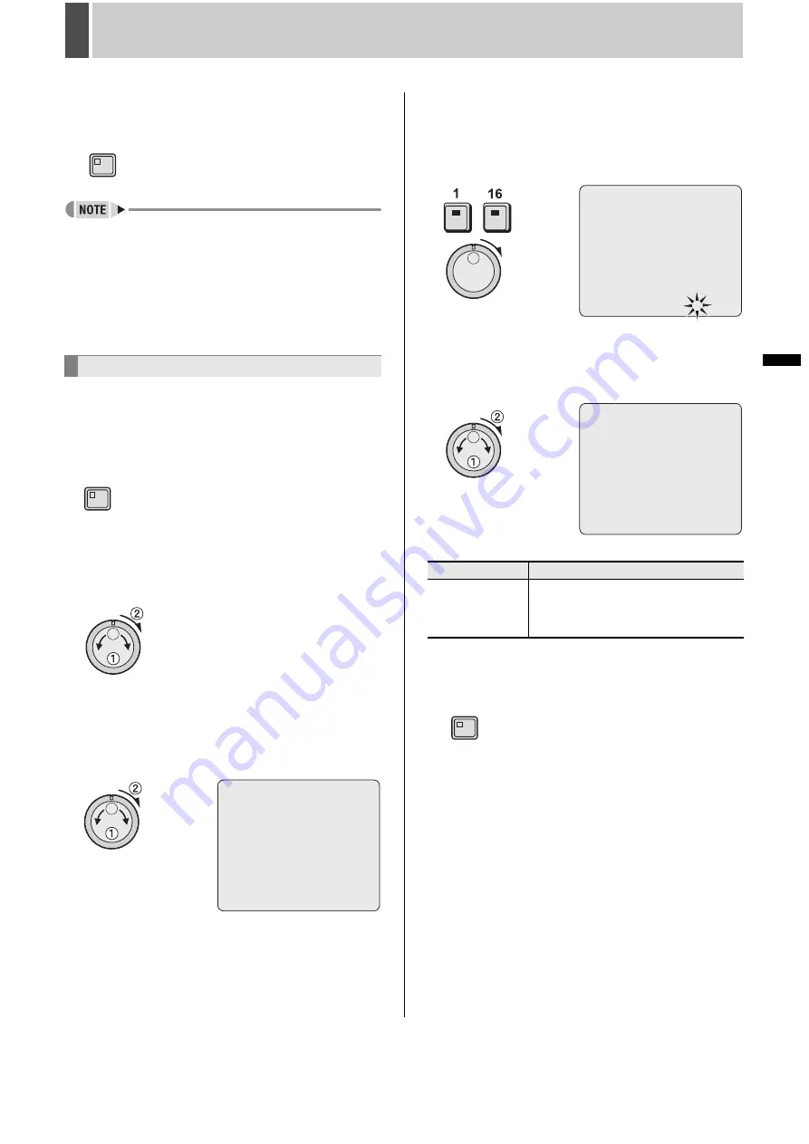
Use the following procedure to adjust the color of video
displayed on monitors.
1
Press the [MENU] button.
The MENU indicator lights up and the <MAIN MENU> is
displayed.
2
Turn the jog dial to select “4.SCREEN
SET” and then turn the shuttle dial
clockwise.
The <SCREEN SET> screen is displayed.
3
Turn the jog dial to select “4.COLOR
LEVEL SET” and then turn the shuttle
dial clockwise.
The <COLOR LEVEL SET> screen is displayed.
4
Press the [CAMERA SELECT] button for
the camera whose color level is to be
set and then turn the shuttle dial
clockwise.
“5” flashes.
5
Turn the jog dial to select the “COLOR
LEVEL” setting and then turn the
shuttle dial clockwise.
-
[Settings] (The default setting is “5”)
6
Press the [EXIT/OSD] button.
The setting is completed and the display returns to the normal
screen.
Setting the color level
EXIT/OSD
MENU
<COLOR LEVEL SET>
CH01 COLOR LEVEL : 5
Setting
Description
1 - 10
Manual adjustment to one of ten levels.
Light (1) to Dark (10)
Display is automatically in color when set
to 10.
<COLOR LEVEL SET>
CH01 COLOR LEVEL : 5
-
<COLOR LEVEL SET>
CH01 COLOR LEVEL : 5
EXIT/OSD
Summary of Contents for DSR-5709P
Page 158: ......
Page 159: ...Manual for Remote Operation by Network Connection ...
Page 235: ......


