125
Chapter 9 MAINTENANCE AND CHECK
9.4.1 PARTS REQUIRED FOR PERIODIC REPLACEMENT
There are parts required for periodic replacement.
PARTS NAME
INTERVAL
MAGNETRON
4,000 HOURS
MOTOR
10,000 HOURS
In many cases, parts required for periodic replacement works interval hours or more,
but if it is over the interval hours it is recommended to replace the early.
The occurrence of phenomenon when parts were consumed)
Magnetron: The radar sensitivity decreases, and it becomes difficult to take the tune.
Motor: Allophone generation and rotation instability or stop.
Parts life time might become remarkably short by vibration of radar mast
more than product standard.
9.5 FAULT FINDING
9.5.1 ALARMS AND OTHER DISPLAY LISTS
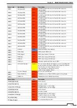
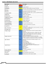
If any of the following alarm occurs, the system displays the alarm message in red in order to attract the
attention of operator. Other messages are displayed with the suitable color which is yellow or blue depending
on the level of message importance.
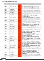
The following table shows alarms and other indications the system displays.
Alarm Code
Alarm Name
Class
Description
S001
Alarm Error
Alarm
Cannot send the alarm because of insufficient message buffer for
alarm task.
S002
Scanner(AZI)
Alarm
The BP error bit of scanner communication data is set.
S003
Scanner(HL)
Alarm
The BZ error bit of scanner communication data is set.
S004
Scanner(MHV)
Alarm
The high-voltage modulator error bit of scanner communication
data is set.
S005
Scanner(Time out)
Alarm
No reply from the scanner after data communication.
S006
Scanner(Data)
Alarm
Collision occurs when transmitting data to the scanner.
Checksum of the received data is different.
S007
Scanner(EEPROM)
Alarm
Stored value error is returned from the scanner when the initial
adjustment data is requested.
The save operation is not completed when data save is
requested to scanner EEPROM.
S008
Scanner(Heater)
Alarm
The MAG heater voltage error bit of scanner communication data
is set.
S009
Scanner(Video)
Alarm
The VIDEO error bit of scanner communication data is set.
S010
Scanner(Trigger)
Alarm
The TRIGGER error bit of scanner communication data is set.
Summary of Contents for SMR-715 series
Page 1: ...MARINE RADAR EQUIPMENT INSTRUCTION MANUAL...
Page 2: ......
Page 15: ...xiii EQUIPMENT APPEARANCE NKE 1066 SCANNER UNIT NKE 2044 SCANNER UNIT...
Page 29: ...Chapter 1 INSTALLATION 3 1 2 3 DIMENSIONAL DRAWING OF DISPLAY MOUNTING...
Page 30: ...Chapter 1 INSTALLATION 4...
Page 32: ...Chapter 1 INSTALLATION 6 DESKTOP MOUNTING TEMPLATE Note Please note the paper size 182 257...
Page 34: ...Chapter 1 INSTALLATION 8 FLUSH MOUNTING TEMPLATE Note Please note the paper size 182 257...
Page 43: ...Chapter 1 INSTALLATION 17 NKE 2044 2FT SCANNER Fig 1 3 6 3 Fig 1 3 6 4...
Page 47: ...Chapter 1 INSTALLATION 21 Fig 1 4 1 3...
Page 51: ...Chapter 1 INSTALLATION 25 Fig 1 4 2 3...
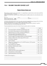
Page 157: ...131 Chapter 10 AFTER SALE SERVICE 10 4 RADAR FAILURE CHECK LIST SMR...
Page 159: ...133 Chapter 12 SPECIFICATIONS Chapter 12 SPECIFICATIONS...
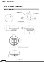
Page 160: ...134 Chapter 12 SPECIFICATIONS 12 1 SCANNER DIMENSION 12 1 1 NKE 1066 4 40 RUBBER PLATE...
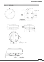
Page 161: ...135 Chapter 12 SPECIFICATIONS 12 1 2 NKE 2044...
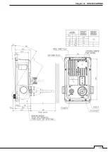
Page 162: ...136 Chapter 12 SPECIFICATIONS 12 2 DISPLAY DIMENSION 12 2 1 SMR 715 720...
Page 163: ...137 Chapter 12 SPECIFICATIONS...
Page 172: ...APPENDIX A 1 APPENDIX NKE 1066 1 5FT SCANNER INTERCONNECTION DIAGRAM FIG A1...
Page 173: ...APPENDIX A 2 NKE 2044 2FT SCANNER INTERCONNECTION DIAGRAM FIG A2...
Page 174: ...APPENDIX A 3 SMR 715 720 DISPLAY UNIT INTER CONNECTION DIAGRAM FIG A3...
Page 175: ...APPENDIX A 4 SMR 715 720 PRIMARY POWER SUPPLY DIAGRAM FIG A4...
Page 176: ...APPENDIX A 5 SMR 715 720 INTERCONNECTION DIAGRAM FIG A5...
Page 177: ...APPENDIX A 6 MEMO...
Page 187: ...APPENDIX A 16 DECLARATION OF CONFORMITY...
Page 188: ...APPENDIX A 17...
Page 189: ...APPENDIX...
Page 191: ...Chapter 3 ADJUST THE RADAR ECHO A 2...
Page 192: ...Chapter 3 ADJUST THE RADAR ECHO...


