119
Chapter 9 MAINTENANCE AND CHECK
Chapter 9 MAINTENANCE AND CHECK
9.1 ROUTINE MAINTENANCE
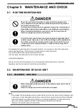
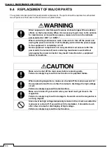
DANGER
Never carry out internal inspection or repair work of the equipment by
users. Inspection or repair work by unauthorized personnel may result in
fire hazard or electric shock.
For inspection and repair work of equipment components, consult with our
branch office, branch shop, sales office, or our distributor in your district.
When conducting maintenance, make sure to turn the main power off.
Failure to comply may result in electrocution.
Turn off the main power before cleaning the equipment. Especially when a
rectifier is used, make sure to turn it off since voltage is still outputted from
the rectifier even after the indicator and the radar are turned off. Failure to
comply may result in equipment failure, or death or serious injury due to
electric shock.
For operating the radar equipment in the good conditions, it is necessary to make the maintenance
work as described below. If maintenance is made properly, troubles will reduce.
It is recommended to make regular maintenance work.
Common points of maintenance for each unit are as follow:
Clean the equipment.
Remove the dust, dirt, and sea water rest on the equipment cabinet with a piece of dry cloth.
Especially, clean the air vents with a brush for good ventilation.
9.2 MAINTENANCE OF EACH UNIT
9.2.1 SCANNER NKE-1066
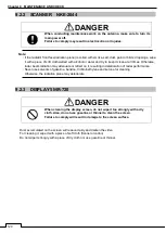
DANGER
When conducting maintenance work on the antenna, make sure to turn its
main power off.
Failure to comply may result in electrocution or injuries.
Note:
・
If the radiator front face(radiation plane) is soiled with smoke, salt, dust, paint or birds
’ droppings, wipe
it with a piece of soft cloth wetted with alcohol or water and try to keep it clean at all times. Otherwise,
radar beam radiation may attenuate or reflect on it, resulting in deterioration of radar performance.
・
Never use solvents of gasoline, benzine, trichloroethylene and ketone for cleaning.
Otherwise, the radiation plane may deteriorate.
Summary of Contents for SMR-715 series
Page 1: ...MARINE RADAR EQUIPMENT INSTRUCTION MANUAL...
Page 2: ......
Page 15: ...xiii EQUIPMENT APPEARANCE NKE 1066 SCANNER UNIT NKE 2044 SCANNER UNIT...
Page 29: ...Chapter 1 INSTALLATION 3 1 2 3 DIMENSIONAL DRAWING OF DISPLAY MOUNTING...
Page 30: ...Chapter 1 INSTALLATION 4...
Page 32: ...Chapter 1 INSTALLATION 6 DESKTOP MOUNTING TEMPLATE Note Please note the paper size 182 257...
Page 34: ...Chapter 1 INSTALLATION 8 FLUSH MOUNTING TEMPLATE Note Please note the paper size 182 257...
Page 43: ...Chapter 1 INSTALLATION 17 NKE 2044 2FT SCANNER Fig 1 3 6 3 Fig 1 3 6 4...
Page 47: ...Chapter 1 INSTALLATION 21 Fig 1 4 1 3...
Page 51: ...Chapter 1 INSTALLATION 25 Fig 1 4 2 3...
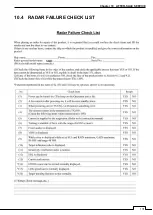
Page 157: ...131 Chapter 10 AFTER SALE SERVICE 10 4 RADAR FAILURE CHECK LIST SMR...
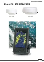
Page 159: ...133 Chapter 12 SPECIFICATIONS Chapter 12 SPECIFICATIONS...
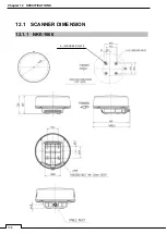
Page 160: ...134 Chapter 12 SPECIFICATIONS 12 1 SCANNER DIMENSION 12 1 1 NKE 1066 4 40 RUBBER PLATE...
Page 161: ...135 Chapter 12 SPECIFICATIONS 12 1 2 NKE 2044...
Page 162: ...136 Chapter 12 SPECIFICATIONS 12 2 DISPLAY DIMENSION 12 2 1 SMR 715 720...
Page 163: ...137 Chapter 12 SPECIFICATIONS...
Page 172: ...APPENDIX A 1 APPENDIX NKE 1066 1 5FT SCANNER INTERCONNECTION DIAGRAM FIG A1...
Page 173: ...APPENDIX A 2 NKE 2044 2FT SCANNER INTERCONNECTION DIAGRAM FIG A2...
Page 174: ...APPENDIX A 3 SMR 715 720 DISPLAY UNIT INTER CONNECTION DIAGRAM FIG A3...
Page 175: ...APPENDIX A 4 SMR 715 720 PRIMARY POWER SUPPLY DIAGRAM FIG A4...
Page 176: ...APPENDIX A 5 SMR 715 720 INTERCONNECTION DIAGRAM FIG A5...
Page 177: ...APPENDIX A 6 MEMO...
Page 187: ...APPENDIX A 16 DECLARATION OF CONFORMITY...
Page 188: ...APPENDIX A 17...
Page 189: ...APPENDIX...
Page 191: ...Chapter 3 ADJUST THE RADAR ECHO A 2...
Page 192: ...Chapter 3 ADJUST THE RADAR ECHO...

