Chapter 1 INSTALLATION
11
1.2.6 EXTERNAL NAVIGATIONAL SIGNAL CONNECTION
(GPS, AIS, GYRO, LOG, etc.) Connecting cable is option
Option NMEA cable: H-7ZCRD1689*
In case of using option NMEA cable, waterproofing (IPX5) is guaranteed. Thus using another NMEA cable,
waterproofing (IPX5) is not guaranteed.
・
Using GPS receiver, please connect NMEA1.
・
Using NSK, please connect NMEA3.
・
AIS connects all NMEA port available.
Navigation system interfaces, such as GPS
Telecommunications standard NMEA0183 / IEC61162-1/2 conformity
Communications protocol: 4800 bps, start 1bit, data 8bit, stop 1bit, and no parity
Input sentence NMEA0183:
V1.5: GGA/ GLL/ RMC
V2.0: GGA/ GLL/ RMC/ ZDA
V2.3: GGA/ GLL/ RMC/ GNS/ ZDA
(Talker= "G P" etc.)
Information ship position and the time; GGA/ GNS/ GLL/ RMC
Day
ZDA
Time of equipment: ZDA/ GGA/ GNS/ GLL/ RMC
Reference :
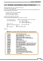
NMEA0183 content outline of standard input / output sentence
$xxACK
Acknowledgement alarm
$xxBWC
Bearing and Distance to Waypoint
$xxCUR
Water current layer
$xxGGA
Global Positioning System Fix Data
$xxGLL
Geographic Position - Latitude/Longitude
$xxGNS
GNSS fix data
$xxMTW
Water temperature
$xxMWD
Wind direction and speed
$xxMWV
Wind speed and angle
$xxRMA
Recommended Minimum Specific LORAN-C data
$xxRMB
Recommended Minimum Navigation Information
$xxRMC
Recommended Minimum Specific GNSS Data
$xxROT
Rate Of Turn
$xxRSA
Rudder Sensor Angle
$xxTHS
True Heading and Status
$xxVBW
Dual ground/water speed
$xxVDM
AIS VHF Data-link Message
$xxVDO
AIS VHF Data-link Own-vessel report
$xxVTG
Course Over Ground and Ground Speed
$xxZDA
Time and Date
Summary of Contents for SMR-715 series
Page 1: ...MARINE RADAR EQUIPMENT INSTRUCTION MANUAL...
Page 2: ......
Page 15: ...xiii EQUIPMENT APPEARANCE NKE 1066 SCANNER UNIT NKE 2044 SCANNER UNIT...
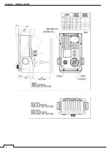
Page 29: ...Chapter 1 INSTALLATION 3 1 2 3 DIMENSIONAL DRAWING OF DISPLAY MOUNTING...
Page 30: ...Chapter 1 INSTALLATION 4...
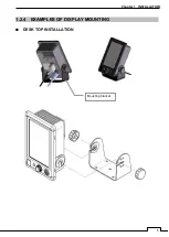
Page 32: ...Chapter 1 INSTALLATION 6 DESKTOP MOUNTING TEMPLATE Note Please note the paper size 182 257...
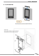
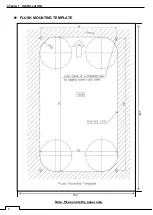
Page 34: ...Chapter 1 INSTALLATION 8 FLUSH MOUNTING TEMPLATE Note Please note the paper size 182 257...
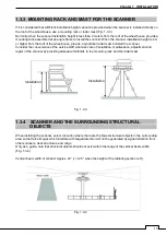
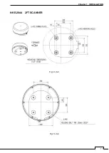
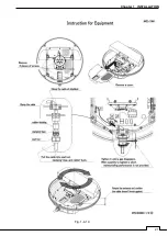
Page 43: ...Chapter 1 INSTALLATION 17 NKE 2044 2FT SCANNER Fig 1 3 6 3 Fig 1 3 6 4...
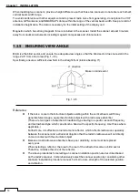
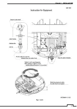
Page 47: ...Chapter 1 INSTALLATION 21 Fig 1 4 1 3...
Page 51: ...Chapter 1 INSTALLATION 25 Fig 1 4 2 3...
Page 157: ...131 Chapter 10 AFTER SALE SERVICE 10 4 RADAR FAILURE CHECK LIST SMR...
Page 159: ...133 Chapter 12 SPECIFICATIONS Chapter 12 SPECIFICATIONS...
Page 160: ...134 Chapter 12 SPECIFICATIONS 12 1 SCANNER DIMENSION 12 1 1 NKE 1066 4 40 RUBBER PLATE...
Page 161: ...135 Chapter 12 SPECIFICATIONS 12 1 2 NKE 2044...
Page 162: ...136 Chapter 12 SPECIFICATIONS 12 2 DISPLAY DIMENSION 12 2 1 SMR 715 720...
Page 163: ...137 Chapter 12 SPECIFICATIONS...
Page 172: ...APPENDIX A 1 APPENDIX NKE 1066 1 5FT SCANNER INTERCONNECTION DIAGRAM FIG A1...
Page 173: ...APPENDIX A 2 NKE 2044 2FT SCANNER INTERCONNECTION DIAGRAM FIG A2...
Page 174: ...APPENDIX A 3 SMR 715 720 DISPLAY UNIT INTER CONNECTION DIAGRAM FIG A3...
Page 175: ...APPENDIX A 4 SMR 715 720 PRIMARY POWER SUPPLY DIAGRAM FIG A4...
Page 176: ...APPENDIX A 5 SMR 715 720 INTERCONNECTION DIAGRAM FIG A5...
Page 177: ...APPENDIX A 6 MEMO...
Page 187: ...APPENDIX A 16 DECLARATION OF CONFORMITY...
Page 188: ...APPENDIX A 17...
Page 189: ...APPENDIX...
Page 191: ...Chapter 3 ADJUST THE RADAR ECHO A 2...
Page 192: ...Chapter 3 ADJUST THE RADAR ECHO...

