77
Chapter 5 VARIOUS FUNCTION ICONS
N
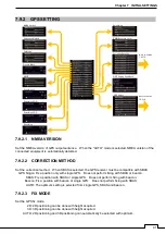
5.17.1 FUNCTION ON/OFF
Turns ON/OFF TT function and AIS function.
5.17.2 CPA LIMIT
Set and check collision decision criteria before operating.
The CPA Limit value can be set between 0.1 and 9.9NM.
5.17.3 TCPA LIMIT
Set and check collision decision criteria before operating.
The TCPA Limit value can be set between 1 and 99 min.
5.17.4 CPA RING DISPLAY
Sets the CPA ring display. While the distance of the specified CPA Limit value is used as the radius, the CPA
ring is displayed with a circle of which center is the own ship’s position. The CPA ring is not displayed when
the true vector mode is selected.
5.17.5 TARGET NUMBER DISPLAY
A target ID number is a value displayed beside the TT symbol or AIS symbol. These numbers are assigned to
targets in acquisition order.
TT is automatically assigned to the 1 to 10 number.
AIS is automatically assigned to the 11 to 60 number.
Each target is identified by the assigned ID number until it is lost or its acquisition is canceled.
5.17.6 ALR ALARM FROM AIS
Sets the display of NMEA ALR sentence received from AIS.
5.17.7 AIS DISPLAY TARGETS
Sets the number of AIS display targets. Set this to get a better look at the screen by limiting the number of
AIS symbols.
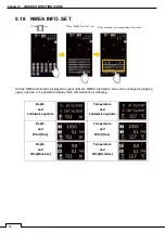
5.17.8 AIS LIST DISPLAY
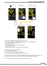
Sets
the AIS List Display. “ON” is selected, then tap icon, AIS list displays as following.
①Tap
icon
1JRC-XX
TOMOYASU MARU
2JRC-XX
MOMOSE MARU
3JRC-XX
SHANG MARU
4JRC-XX
MATSUZAKI GO
5JRC-XX
DAISAN TAKE MARU
②AIS LIST appear
Summary of Contents for SMR-715 series
Page 1: ...MARINE RADAR EQUIPMENT INSTRUCTION MANUAL...
Page 2: ......
Page 15: ...xiii EQUIPMENT APPEARANCE NKE 1066 SCANNER UNIT NKE 2044 SCANNER UNIT...
Page 29: ...Chapter 1 INSTALLATION 3 1 2 3 DIMENSIONAL DRAWING OF DISPLAY MOUNTING...
Page 30: ...Chapter 1 INSTALLATION 4...
Page 32: ...Chapter 1 INSTALLATION 6 DESKTOP MOUNTING TEMPLATE Note Please note the paper size 182 257...
Page 34: ...Chapter 1 INSTALLATION 8 FLUSH MOUNTING TEMPLATE Note Please note the paper size 182 257...
Page 43: ...Chapter 1 INSTALLATION 17 NKE 2044 2FT SCANNER Fig 1 3 6 3 Fig 1 3 6 4...
Page 47: ...Chapter 1 INSTALLATION 21 Fig 1 4 1 3...
Page 51: ...Chapter 1 INSTALLATION 25 Fig 1 4 2 3...
Page 157: ...131 Chapter 10 AFTER SALE SERVICE 10 4 RADAR FAILURE CHECK LIST SMR...
Page 159: ...133 Chapter 12 SPECIFICATIONS Chapter 12 SPECIFICATIONS...
Page 160: ...134 Chapter 12 SPECIFICATIONS 12 1 SCANNER DIMENSION 12 1 1 NKE 1066 4 40 RUBBER PLATE...
Page 161: ...135 Chapter 12 SPECIFICATIONS 12 1 2 NKE 2044...
Page 162: ...136 Chapter 12 SPECIFICATIONS 12 2 DISPLAY DIMENSION 12 2 1 SMR 715 720...
Page 163: ...137 Chapter 12 SPECIFICATIONS...
Page 172: ...APPENDIX A 1 APPENDIX NKE 1066 1 5FT SCANNER INTERCONNECTION DIAGRAM FIG A1...
Page 173: ...APPENDIX A 2 NKE 2044 2FT SCANNER INTERCONNECTION DIAGRAM FIG A2...
Page 174: ...APPENDIX A 3 SMR 715 720 DISPLAY UNIT INTER CONNECTION DIAGRAM FIG A3...
Page 175: ...APPENDIX A 4 SMR 715 720 PRIMARY POWER SUPPLY DIAGRAM FIG A4...
Page 176: ...APPENDIX A 5 SMR 715 720 INTERCONNECTION DIAGRAM FIG A5...
Page 177: ...APPENDIX A 6 MEMO...
Page 187: ...APPENDIX A 16 DECLARATION OF CONFORMITY...
Page 188: ...APPENDIX A 17...
Page 189: ...APPENDIX...
Page 191: ...Chapter 3 ADJUST THE RADAR ECHO A 2...
Page 192: ...Chapter 3 ADJUST THE RADAR ECHO...

