95
Chapter 7 INITIAL SETTINGS
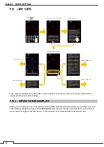
7.9.3 BEACON SETTING
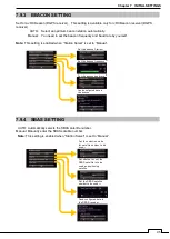
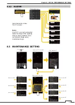
Set for a JRC Beacon (DGPS receiver). This setting is available only for JRC Beacon receiver (DGPS
receiver).
AUTO: Select an optimum beacon station automatically.
Manual: You need to set the beacon frequency and baud rate by yourself.
Note:
This setting is enabled
when “Station Select” is set to “Manual”.
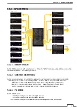
7.9.4 SBAS SETTING
AUTO: Automatically selects the SBAS satellite number.
Manual: Manually enter the SBAS satellite number.
Note:
This setting is enabled
when “Station Select” is set to ”Manual”.
Set the beacon Station.
*
Set the beacon frequency.
**
Set the beacon baud rate.
**
Send configured data to
the beacon.
Set the selection mode
for satellite number to be
used.
*
Set whether or not the
SBAS satellite is to be
used as positioning
satellite.
Set the SBAS satellite
number to be used.
**
Send configured data to
the SBAS receiver.
Summary of Contents for SMR-715 series
Page 1: ...MARINE RADAR EQUIPMENT INSTRUCTION MANUAL...
Page 2: ......
Page 15: ...xiii EQUIPMENT APPEARANCE NKE 1066 SCANNER UNIT NKE 2044 SCANNER UNIT...
Page 29: ...Chapter 1 INSTALLATION 3 1 2 3 DIMENSIONAL DRAWING OF DISPLAY MOUNTING...
Page 30: ...Chapter 1 INSTALLATION 4...
Page 32: ...Chapter 1 INSTALLATION 6 DESKTOP MOUNTING TEMPLATE Note Please note the paper size 182 257...
Page 34: ...Chapter 1 INSTALLATION 8 FLUSH MOUNTING TEMPLATE Note Please note the paper size 182 257...
Page 43: ...Chapter 1 INSTALLATION 17 NKE 2044 2FT SCANNER Fig 1 3 6 3 Fig 1 3 6 4...
Page 47: ...Chapter 1 INSTALLATION 21 Fig 1 4 1 3...
Page 51: ...Chapter 1 INSTALLATION 25 Fig 1 4 2 3...
Page 157: ...131 Chapter 10 AFTER SALE SERVICE 10 4 RADAR FAILURE CHECK LIST SMR...
Page 159: ...133 Chapter 12 SPECIFICATIONS Chapter 12 SPECIFICATIONS...
Page 160: ...134 Chapter 12 SPECIFICATIONS 12 1 SCANNER DIMENSION 12 1 1 NKE 1066 4 40 RUBBER PLATE...
Page 161: ...135 Chapter 12 SPECIFICATIONS 12 1 2 NKE 2044...
Page 162: ...136 Chapter 12 SPECIFICATIONS 12 2 DISPLAY DIMENSION 12 2 1 SMR 715 720...
Page 163: ...137 Chapter 12 SPECIFICATIONS...
Page 172: ...APPENDIX A 1 APPENDIX NKE 1066 1 5FT SCANNER INTERCONNECTION DIAGRAM FIG A1...
Page 173: ...APPENDIX A 2 NKE 2044 2FT SCANNER INTERCONNECTION DIAGRAM FIG A2...
Page 174: ...APPENDIX A 3 SMR 715 720 DISPLAY UNIT INTER CONNECTION DIAGRAM FIG A3...
Page 175: ...APPENDIX A 4 SMR 715 720 PRIMARY POWER SUPPLY DIAGRAM FIG A4...
Page 176: ...APPENDIX A 5 SMR 715 720 INTERCONNECTION DIAGRAM FIG A5...
Page 177: ...APPENDIX A 6 MEMO...
Page 187: ...APPENDIX A 16 DECLARATION OF CONFORMITY...
Page 188: ...APPENDIX A 17...
Page 189: ...APPENDIX...
Page 191: ...Chapter 3 ADJUST THE RADAR ECHO A 2...
Page 192: ...Chapter 3 ADJUST THE RADAR ECHO...


