GLOSSARY
xxii
F
fm
fathom 1fm=1.8288m
FTC
Fast Time Constant
Function of FTC reduces the effect of long duration returns that come from rain or snow.
G
GPS
Global Positioning System
GPS is a space-based satellite navigation system that provides location and time
information in all weather conditions.
Ground stabilization
A display mode in which speed and course information are referred to the ground, using
ground track input data.
Gyrocompass
A gyrocompass is non-magnetic compass which is based on a fast
spinning disc and
rotation of the Earth to automatically find north and south direction.
H
HDG
Heading
The horizontal direction that the bow of a ship is pointing at any instant, expressed in angular
units from a reference direction.
HDOP
Horizontal Dilution of Precision
The accuracy of the position. If the value is small, the accuracy of position is high.
HL
Heading line
A graphic line on a radar presentation drawn from the consistent common reference point
to the bearing scale to indicate the heading of the ship
H up
Head up
Own shi
p’s heading line is always pointed to the top center of the radar display.
I
IR
Radar Interference Rejecter
L
LL
Latitude/ Longitude coordinate system
Log
A device measures the speed through the water.
Lost AIS target
A target symbol representing the last valid position of an AIS target before the reception of its
data was lost, or its last dead-reckoned position.
Lost tracked target
One for which target information is no longer available due to poor, lost or obscured signals.
LP
Long Pulse
M
MMSI
Maritime Mobile Service Identity
MOB
Man Over Board
MP
Medium Pulse
N
NM
1NM=1852m
NMEA
National Marine Electronics Association
NSK
North Stabilization Kit
N up
North up
The north is always pointed to the top center of the radar display.
O
Own track
Display function of own ship
’s track
Summary of Contents for SMR-715 series
Page 1: ...MARINE RADAR EQUIPMENT INSTRUCTION MANUAL...
Page 2: ......
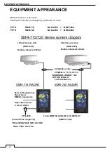
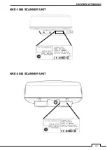
Page 15: ...xiii EQUIPMENT APPEARANCE NKE 1066 SCANNER UNIT NKE 2044 SCANNER UNIT...
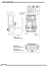
Page 29: ...Chapter 1 INSTALLATION 3 1 2 3 DIMENSIONAL DRAWING OF DISPLAY MOUNTING...
Page 30: ...Chapter 1 INSTALLATION 4...
Page 32: ...Chapter 1 INSTALLATION 6 DESKTOP MOUNTING TEMPLATE Note Please note the paper size 182 257...
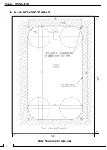
Page 34: ...Chapter 1 INSTALLATION 8 FLUSH MOUNTING TEMPLATE Note Please note the paper size 182 257...
Page 43: ...Chapter 1 INSTALLATION 17 NKE 2044 2FT SCANNER Fig 1 3 6 3 Fig 1 3 6 4...
Page 47: ...Chapter 1 INSTALLATION 21 Fig 1 4 1 3...
Page 51: ...Chapter 1 INSTALLATION 25 Fig 1 4 2 3...
Page 157: ...131 Chapter 10 AFTER SALE SERVICE 10 4 RADAR FAILURE CHECK LIST SMR...
Page 159: ...133 Chapter 12 SPECIFICATIONS Chapter 12 SPECIFICATIONS...
Page 160: ...134 Chapter 12 SPECIFICATIONS 12 1 SCANNER DIMENSION 12 1 1 NKE 1066 4 40 RUBBER PLATE...
Page 161: ...135 Chapter 12 SPECIFICATIONS 12 1 2 NKE 2044...
Page 162: ...136 Chapter 12 SPECIFICATIONS 12 2 DISPLAY DIMENSION 12 2 1 SMR 715 720...
Page 163: ...137 Chapter 12 SPECIFICATIONS...
Page 172: ...APPENDIX A 1 APPENDIX NKE 1066 1 5FT SCANNER INTERCONNECTION DIAGRAM FIG A1...
Page 173: ...APPENDIX A 2 NKE 2044 2FT SCANNER INTERCONNECTION DIAGRAM FIG A2...
Page 174: ...APPENDIX A 3 SMR 715 720 DISPLAY UNIT INTER CONNECTION DIAGRAM FIG A3...
Page 175: ...APPENDIX A 4 SMR 715 720 PRIMARY POWER SUPPLY DIAGRAM FIG A4...
Page 176: ...APPENDIX A 5 SMR 715 720 INTERCONNECTION DIAGRAM FIG A5...
Page 177: ...APPENDIX A 6 MEMO...
Page 187: ...APPENDIX A 16 DECLARATION OF CONFORMITY...
Page 188: ...APPENDIX A 17...
Page 189: ...APPENDIX...
Page 191: ...Chapter 3 ADJUST THE RADAR ECHO A 2...
Page 192: ...Chapter 3 ADJUST THE RADAR ECHO...

