142
Chapter 12 SPECIFICATIONS
12.6 DISPLAY
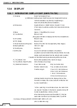
12.6.1 INTEGRATED DISPLAY UNIT (SMR-715/720)
1) Structure
Desk Top Integrated Type
(LCD Monitor Unit/Keyboard Unit/Processor Unit Integrated Structure)
Vertical installation only desk top integrated type
Option: Overhead Mounted kit installation
2) Dimensions
Height 235.2mm × Width 162mm × Depth 77.3mm
(The U style mount base and the both sides knob bolts are
included.)
3) Mass
Approx. 1.7kg(Without Sun cover)
4) Tune Method
Manual / Auto
(Bar-graph indication is displayed at the time of adjustment.)
5) STC (SEA)
Manual / Auto
6) FTC (RAIN)
Manual / Auto
7) Radar Interference Rejection
Built-in (The effect can be adjusted by three stages.)
8) Bearing Marker
360° in 5° digit
9) Heading Line
Electronic
10) Off Center
move to the defined coordinates of 4 patterns
(4 patterns are back side 64dots,left side 92dots, front side
92dots, right side 92dots from the default center position)
Transition of the radar trails is possible during Off Center mode.
11) True Motion Unit
Built-in (Not available at the maximum range)
12) True Motion Reset Position
40% of radius of any range
13) Radar trail indication
True motion mode:
Only true motion trails
Relative motion mode:
True or relative motion trails
Trail time length:
15 sec to 15 min/Continuous
30 sec to 30 min/Continuous
1 min to 1 hr/Continuous
30 min to 24 hr/Continuous
Arbitrary trail time length can be displayed at any time.
Possible to display time series trail and continuous trail
by color classification.
* When switching to true/relative trails, the radar trails
are cleared. Transition of the trails is possible during Off
Center mode (Relative motion). (Scroll)
When the bearing mode is switched (RM (T), TM), the
radar trails are taken over at between RM (T) and TM.
14) Variety of Pulse width SP1/ SP2/ SP3/ MP1/ MP2/ LP1/ LP2
(LP2 is JMA-1034 only)
Summary of Contents for SMR-715 series
Page 1: ...MARINE RADAR EQUIPMENT INSTRUCTION MANUAL...
Page 2: ......
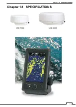
Page 15: ...xiii EQUIPMENT APPEARANCE NKE 1066 SCANNER UNIT NKE 2044 SCANNER UNIT...
Page 29: ...Chapter 1 INSTALLATION 3 1 2 3 DIMENSIONAL DRAWING OF DISPLAY MOUNTING...
Page 30: ...Chapter 1 INSTALLATION 4...
Page 32: ...Chapter 1 INSTALLATION 6 DESKTOP MOUNTING TEMPLATE Note Please note the paper size 182 257...
Page 34: ...Chapter 1 INSTALLATION 8 FLUSH MOUNTING TEMPLATE Note Please note the paper size 182 257...
Page 43: ...Chapter 1 INSTALLATION 17 NKE 2044 2FT SCANNER Fig 1 3 6 3 Fig 1 3 6 4...
Page 47: ...Chapter 1 INSTALLATION 21 Fig 1 4 1 3...
Page 51: ...Chapter 1 INSTALLATION 25 Fig 1 4 2 3...
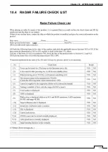
Page 157: ...131 Chapter 10 AFTER SALE SERVICE 10 4 RADAR FAILURE CHECK LIST SMR...
Page 159: ...133 Chapter 12 SPECIFICATIONS Chapter 12 SPECIFICATIONS...
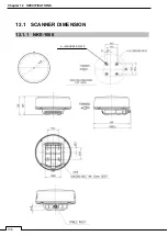
Page 160: ...134 Chapter 12 SPECIFICATIONS 12 1 SCANNER DIMENSION 12 1 1 NKE 1066 4 40 RUBBER PLATE...
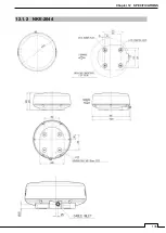
Page 161: ...135 Chapter 12 SPECIFICATIONS 12 1 2 NKE 2044...
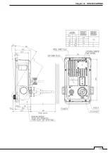
Page 162: ...136 Chapter 12 SPECIFICATIONS 12 2 DISPLAY DIMENSION 12 2 1 SMR 715 720...
Page 163: ...137 Chapter 12 SPECIFICATIONS...
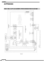
Page 172: ...APPENDIX A 1 APPENDIX NKE 1066 1 5FT SCANNER INTERCONNECTION DIAGRAM FIG A1...
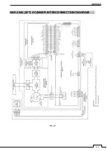
Page 173: ...APPENDIX A 2 NKE 2044 2FT SCANNER INTERCONNECTION DIAGRAM FIG A2...
Page 174: ...APPENDIX A 3 SMR 715 720 DISPLAY UNIT INTER CONNECTION DIAGRAM FIG A3...
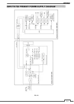
Page 175: ...APPENDIX A 4 SMR 715 720 PRIMARY POWER SUPPLY DIAGRAM FIG A4...
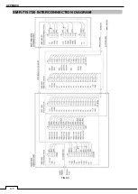
Page 176: ...APPENDIX A 5 SMR 715 720 INTERCONNECTION DIAGRAM FIG A5...
Page 177: ...APPENDIX A 6 MEMO...
Page 187: ...APPENDIX A 16 DECLARATION OF CONFORMITY...
Page 188: ...APPENDIX A 17...
Page 189: ...APPENDIX...
Page 191: ...Chapter 3 ADJUST THE RADAR ECHO A 2...
Page 192: ...Chapter 3 ADJUST THE RADAR ECHO...

