107
Chapter 8 DETAIL PERFORMANCE SETTINGS
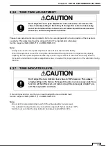
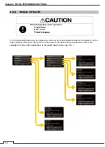
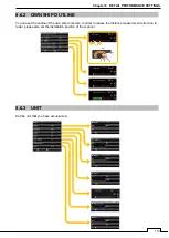
8.5.3 SYSTEM TIME CLEAR
If you press YES, the operation will be executed immediately.
The operating time of the display unit can be initialized.
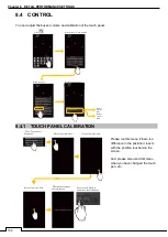
8.5.4 SCANNER TIME CLEAR
Initialize the transmit time when
magnetron is replaced.
Initialize the transmit time when
motor is replaced.
Initialize the Scanner Running time.
Initialize the Transmit time.
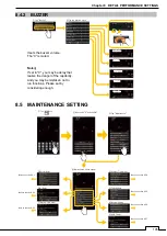
Save the following scanner time data stored in the scanner into the display unit.
Scanner Transmit Time
Motor Rotating Time
When replacing the scanner internal control circuit, perform the procedure below to inherit scanner time data.
1. Save the scanner time data.
2. Replace the scanner internal control circuit.
3. Restore the scanner time data.
Restore the scanner time data stored in the display unit into the scanner internal control circuit.
Initialize those operating time above when magnetron or scanner motor is replaced.
Summary of Contents for SMR-715 series
Page 1: ...MARINE RADAR EQUIPMENT INSTRUCTION MANUAL...
Page 2: ......
Page 15: ...xiii EQUIPMENT APPEARANCE NKE 1066 SCANNER UNIT NKE 2044 SCANNER UNIT...
Page 29: ...Chapter 1 INSTALLATION 3 1 2 3 DIMENSIONAL DRAWING OF DISPLAY MOUNTING...
Page 30: ...Chapter 1 INSTALLATION 4...
Page 32: ...Chapter 1 INSTALLATION 6 DESKTOP MOUNTING TEMPLATE Note Please note the paper size 182 257...
Page 34: ...Chapter 1 INSTALLATION 8 FLUSH MOUNTING TEMPLATE Note Please note the paper size 182 257...
Page 43: ...Chapter 1 INSTALLATION 17 NKE 2044 2FT SCANNER Fig 1 3 6 3 Fig 1 3 6 4...
Page 47: ...Chapter 1 INSTALLATION 21 Fig 1 4 1 3...
Page 51: ...Chapter 1 INSTALLATION 25 Fig 1 4 2 3...
Page 157: ...131 Chapter 10 AFTER SALE SERVICE 10 4 RADAR FAILURE CHECK LIST SMR...
Page 159: ...133 Chapter 12 SPECIFICATIONS Chapter 12 SPECIFICATIONS...
Page 160: ...134 Chapter 12 SPECIFICATIONS 12 1 SCANNER DIMENSION 12 1 1 NKE 1066 4 40 RUBBER PLATE...
Page 161: ...135 Chapter 12 SPECIFICATIONS 12 1 2 NKE 2044...
Page 162: ...136 Chapter 12 SPECIFICATIONS 12 2 DISPLAY DIMENSION 12 2 1 SMR 715 720...
Page 163: ...137 Chapter 12 SPECIFICATIONS...
Page 172: ...APPENDIX A 1 APPENDIX NKE 1066 1 5FT SCANNER INTERCONNECTION DIAGRAM FIG A1...
Page 173: ...APPENDIX A 2 NKE 2044 2FT SCANNER INTERCONNECTION DIAGRAM FIG A2...
Page 174: ...APPENDIX A 3 SMR 715 720 DISPLAY UNIT INTER CONNECTION DIAGRAM FIG A3...
Page 175: ...APPENDIX A 4 SMR 715 720 PRIMARY POWER SUPPLY DIAGRAM FIG A4...
Page 176: ...APPENDIX A 5 SMR 715 720 INTERCONNECTION DIAGRAM FIG A5...
Page 177: ...APPENDIX A 6 MEMO...
Page 187: ...APPENDIX A 16 DECLARATION OF CONFORMITY...
Page 188: ...APPENDIX A 17...
Page 189: ...APPENDIX...
Page 191: ...Chapter 3 ADJUST THE RADAR ECHO A 2...
Page 192: ...Chapter 3 ADJUST THE RADAR ECHO...


