GLOSSARY
xxiv
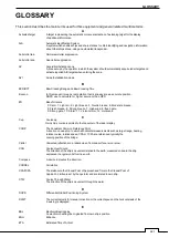
SP
Short Pulse
STAB
Stabilization
STC
Sensitivity Time Control
Function of STC reduces the impact of returns from sea state of relatively near from own ship.
STW
Speed Through Water
The speed of the ship relative to the water surface.
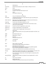
T
TCPA
Time to Closest Point of Approach to own ship
Test target
Radar target of known characteristics used for test requirement
TM
True Motion
A display across which own ship moves with its own true motion.
Trails
Display Radar Trails (Other Ships' Trails)
True course
The direction of motion relative to ground or to sea, of a target expressed as an angular
displacement from north
True speed
The speed of a target relative to ground, or to sea
True vector
A vector representing the predicted true motion of a target, showing course and speed with
reference to the ground or sea
TT
Target Tracking
A computer process of observing the sequential changes in the position of a radar target in
order to establish its motion. Such a target is a Tracked Target.
TTG
Time To Go
Time to next waypoint.
TXRX
Transceiver Unit
U
UTC
Universal Time Coordinated
The international standard of time, kept by atomic clocks around the world.
USB
Universal Serial Bus
USB was designed to standardize the connection of computer peripherals.
V
VRM
Variable Range Marker
An adjustable range ring used to measure the distance to a target.
W
Waypoint
A geographical location on a route indicating an event
Summary of Contents for SMR-715 series
Page 1: ...MARINE RADAR EQUIPMENT INSTRUCTION MANUAL...
Page 2: ......
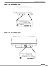
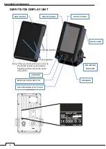
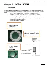
Page 15: ...xiii EQUIPMENT APPEARANCE NKE 1066 SCANNER UNIT NKE 2044 SCANNER UNIT...
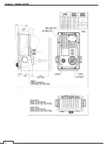
Page 29: ...Chapter 1 INSTALLATION 3 1 2 3 DIMENSIONAL DRAWING OF DISPLAY MOUNTING...
Page 30: ...Chapter 1 INSTALLATION 4...
Page 32: ...Chapter 1 INSTALLATION 6 DESKTOP MOUNTING TEMPLATE Note Please note the paper size 182 257...
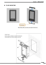
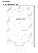
Page 34: ...Chapter 1 INSTALLATION 8 FLUSH MOUNTING TEMPLATE Note Please note the paper size 182 257...
Page 43: ...Chapter 1 INSTALLATION 17 NKE 2044 2FT SCANNER Fig 1 3 6 3 Fig 1 3 6 4...
Page 47: ...Chapter 1 INSTALLATION 21 Fig 1 4 1 3...
Page 51: ...Chapter 1 INSTALLATION 25 Fig 1 4 2 3...
Page 157: ...131 Chapter 10 AFTER SALE SERVICE 10 4 RADAR FAILURE CHECK LIST SMR...
Page 159: ...133 Chapter 12 SPECIFICATIONS Chapter 12 SPECIFICATIONS...
Page 160: ...134 Chapter 12 SPECIFICATIONS 12 1 SCANNER DIMENSION 12 1 1 NKE 1066 4 40 RUBBER PLATE...
Page 161: ...135 Chapter 12 SPECIFICATIONS 12 1 2 NKE 2044...
Page 162: ...136 Chapter 12 SPECIFICATIONS 12 2 DISPLAY DIMENSION 12 2 1 SMR 715 720...
Page 163: ...137 Chapter 12 SPECIFICATIONS...
Page 172: ...APPENDIX A 1 APPENDIX NKE 1066 1 5FT SCANNER INTERCONNECTION DIAGRAM FIG A1...
Page 173: ...APPENDIX A 2 NKE 2044 2FT SCANNER INTERCONNECTION DIAGRAM FIG A2...
Page 174: ...APPENDIX A 3 SMR 715 720 DISPLAY UNIT INTER CONNECTION DIAGRAM FIG A3...
Page 175: ...APPENDIX A 4 SMR 715 720 PRIMARY POWER SUPPLY DIAGRAM FIG A4...
Page 176: ...APPENDIX A 5 SMR 715 720 INTERCONNECTION DIAGRAM FIG A5...
Page 177: ...APPENDIX A 6 MEMO...
Page 187: ...APPENDIX A 16 DECLARATION OF CONFORMITY...
Page 188: ...APPENDIX A 17...
Page 189: ...APPENDIX...
Page 191: ...Chapter 3 ADJUST THE RADAR ECHO A 2...
Page 192: ...Chapter 3 ADJUST THE RADAR ECHO...

