


29
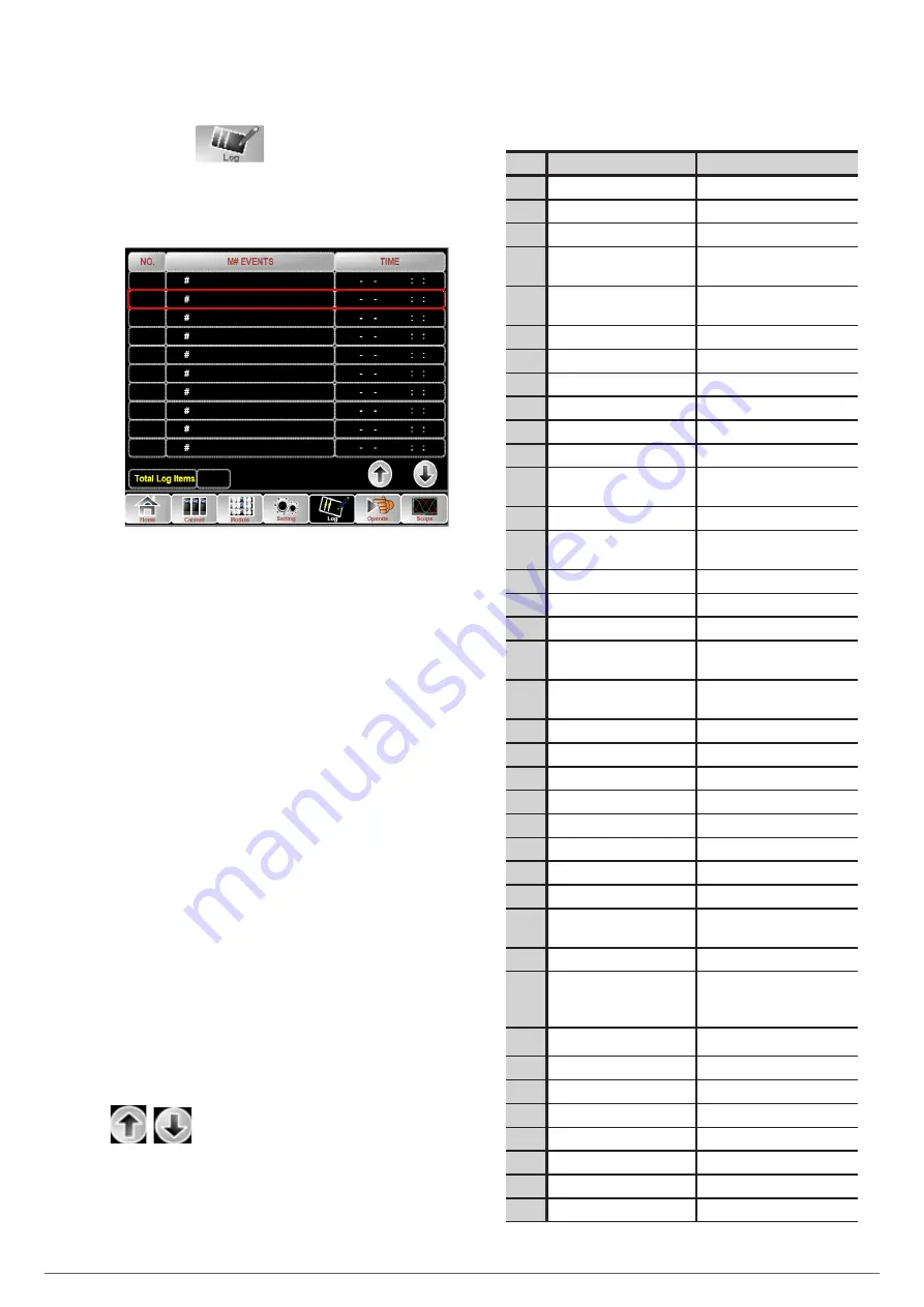
7.5.4. Log
Touch the icon
, (At the bottom of the screen), and
the system enters the interface of the Log, as it is shown in
Fig.47. The log is listed in reverse chronological order, which
displays the events ,warnings and faults information and the
time they occur and disappear.
2014 2 14
2014 2 14
2014 2 14
2014 2 14
2014 2
2014 2 14
2014 2
2014 2
14
14
14
2014 2 14
2014 2 14
29
Load On UPS-Set
Module-Exit-Set
Byp Freq Over Track-Set
Load On Bypass-Set
Bypass Volt Abnormal-Set
Load On Bypass-Set
No Load-Set
Load On Bypass-Set
Byp Freq Over Track-Set
Module Inserted-Set
0
4
0
0
0
0
0
4
0
4
1
2
3
5
6
7
4
8
9
10
16 26 1
16 24 27
16 22 31
16 21 33
16 21 33
16 19 41
16 18 45
16 18 45
16 18 45
16 26 1
Fig. 47.
Log menu
Every incident recorded in the table includes the sequence
number, the content of the incident and the time when it oc-
curs, as is marked in the red box.
•
Sequence number
The serial number for the incident.
•
Content of the incident
Display the information of events, warnings and faults. (0#
means the event happens to the cabinet, n# means the infor-
mation is sent by the nth power module.)
•
Time for the Event
The time the incident occurs.
•
Total Log Items
Display the total number of incidents. The system can record
895 incidents. If the number exceeds 895, the system will de-
lete the earliest incidents.
Turn the list page up/down to check the information of the in-
cidents.
The Table 19 below displays all the incidents and gives a brief
explanation.
Sq.
LCD Display
Explanation
1
Load On UPS-Set
Load On UPS
2
Load On Bypass-Set
Load On Bypass
3
No Load-Set
No Load (Output Power Lost)
4
Battery Boost-Set
Charger is Boosting Battery
Voltage
5
Battery Float-Set
Charger is Floating Battery
Voltage
6
Battery Discharge-Set
Battery is Discharging
7
Battery Connected-Set
Battery cables Connected
8
Battery Not Connected-Set
Battery cables Disconnected.
9
Maintenance CB Closed-Set
Maintenance CB is Closed
10
Maintenance CB Open-Set
Maintenance CB is Open
11
EPO-Set
Emergency Power Off
12
Module On Less-Set
Valid Inverter capacity is less
then the load capacity
13
Module On Less-Clear
Incident above disappears
14
Generator Input-Set
Generator as the Ac Input
Source
15
Generator Input-Clear
Incident above disappears
16
Utility Abnormal-Set
Utility (Grid) Abnormal
17
Utility Abnormal-Clear
Incident above disappears
18
Bypass Sequence Error-Set
Bypass voltage Sequence is
reverse
19
Bypass Sequence Error-
Clear
Incident above disappears
20
Bypass Volt Abnormal-Set
Bypass Voltage Abnormal
21
Bypass Volt Abnormal-Clear
Incident above disappears
22
Bypass Module Fail-Set
Bypass Module Fail
23
Bypass Module Fail-Clear
Incident above disappears
24
Bypass Overload-Set
Bypass Over load
25
Bypass Overload-Clear
Incident above disappears
26
Bypass Overload Tout-Set
Bypass Over Load Timeout
27
Byp Overload Tout-Clear
Incident above disappears
28
Byp Freq Over Track-Set
Bypass Frequency Over Track
Range
29
Byp Freq Over Track-Clear
Incident above disappears
30
Exceed Tx Times Lmt-Set
Transfer times (from inverter
to bypass) in 1 hour exceed
the limit.
31
Exceed Tx Times Lmt-Clear
Incident above disappears
32
Output Short Circuit-Set
Output shorted Circuit
33
Output Short Circuit-Clear
Incident above disappears
34
Battery EOD-Set
Battery End Of Discharge
35
Battery EOD-Clear
Incident above disappears
36
Battery Test-Set
Battery Test Starts
37
Battery Test OK-Set
Battery Test OK
38
Battery Test Fail-Set
Battery Test fails
ADAPT
UNINTERRUPTIBLE POWER SUPPLY
USER'S MANUAL