


13
6. POSITIONING
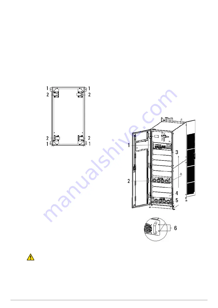
6.1. POSITIONING CABINET
The UPS cabinet has two way of supporting itself: One is to sup-
port itself temporarily by the four wheels at the bottom, making
it convenient to adjust the position of the cabinet; The other is
by anchor bolts to support the cabinet permanently after ad-
justing the position of the cabinet. The supporting structure is
shown in Fig. 19.
1- Anchor bolts
2- Wheels
Fig. 19.
Supporting structure (Bottom view).
The steps to position the cabinet are as follows:
1.
Ensure the supporting structure is in good condition and the
mounting floor is smooth and strong.
2.
Retract the anchor bolts by turning them counterclockwise
using wrench, the cabinet is then supported by the four
wheels.
3.
Adjust the cabinet to the right position by the supporting
wheels.
4.
Put down the anchor bolts by turning them clockwise using
wrench, the cabinet is then supported by the four anchor
bolts.
5.
Ensure the four anchor bolts are in the same height and the
cabinet is fixed and immovable.
6.
Positioning done.
Attention:
Auxiliary equipment is needed when the mounting floor is not
solid enough to support the cabinet, which helps distribute the
weight over a larger area. For instance, cover the floor with iron
plate or increase the supporting area of the anchor bolts.
6.2. INSTALLING POWER MODULE
The installation position of power module is shown in Fig. 20.
Please install the power modules following the principle of
from bottom to top to prevent inclination of the cabinet due to
high center of gravity. The steps of installing power module are
as follows:
1.
Ensure the cabinet is fixed and no damage to the body and
inserting port of the power module.
2.
Hold the handler and the body of the power module by two
persons at each side.
3.
Insert the module in the installation position, and push it
into the cabinet smoothly.
4.
Fix the module to the cabinet though the mounting holes
on two sides of the front plate of the module (See Fig. 20
right).
5.
Installing Power Module done.
1-Bypass module
2- Power module
3-10# Power module
4- 2# Power module
5- 1# Power module
6- Mounting holes
Fig. 20.
Installing power module
ADAPT
UNINTERRUPTIBLE POWER SUPPLY
USER'S MANUAL