


15
6.5. POWER CABLES
6.5.1. Specifications
The «Recommended installation» information for each input
and output setting is available with the supplied documenta-
tion, manual and/or CD. In that information is shown the circuit dia-
gram, as well as the protection size and minimum cross section of the
wires that are connected to the equipment, taking into account the
nominal operating voltage. All figures are calculated for a
maximum
total cable length of 30 m
between the distribution panel board,
equipment and loads.
•
For longer lengths correct the cross sections accordingly, in
order to avoid dropping voltages, by respecting the Regula-
tions or norms corresponding to the country.
•
In the own documentation and for each setting, it is avail-
able the information for «N» units in parallel, as well as the
features of the own «Backfeed protection».
6.5.2. Power switch
From the initials CB in English (Circuit Breakers), the recom-
mendations are the following:
POSITION
150KVA
300KVA
Input switch
300A/3P
600A/3P
Bypass input
switch
250A/3P
500A/3P
Output switch
250A/3P
500A/3P
Batteries switch
400A,250Vdc
800A,250Vdc
Tabla 3.
Recommendations
Attention:
The CB with RCD (Residual Current Device) is not suggested
for the system.
6.5.3. Connecting Power Cables
The steps of connecting power cables are as follows:
1.
Verify that all the external input distribution switches of the
UPS are completely open and the UPS internal maintenance
bypass switch is opened. Attach necessary warning signs
to these switches to prevent unauthorized operation.
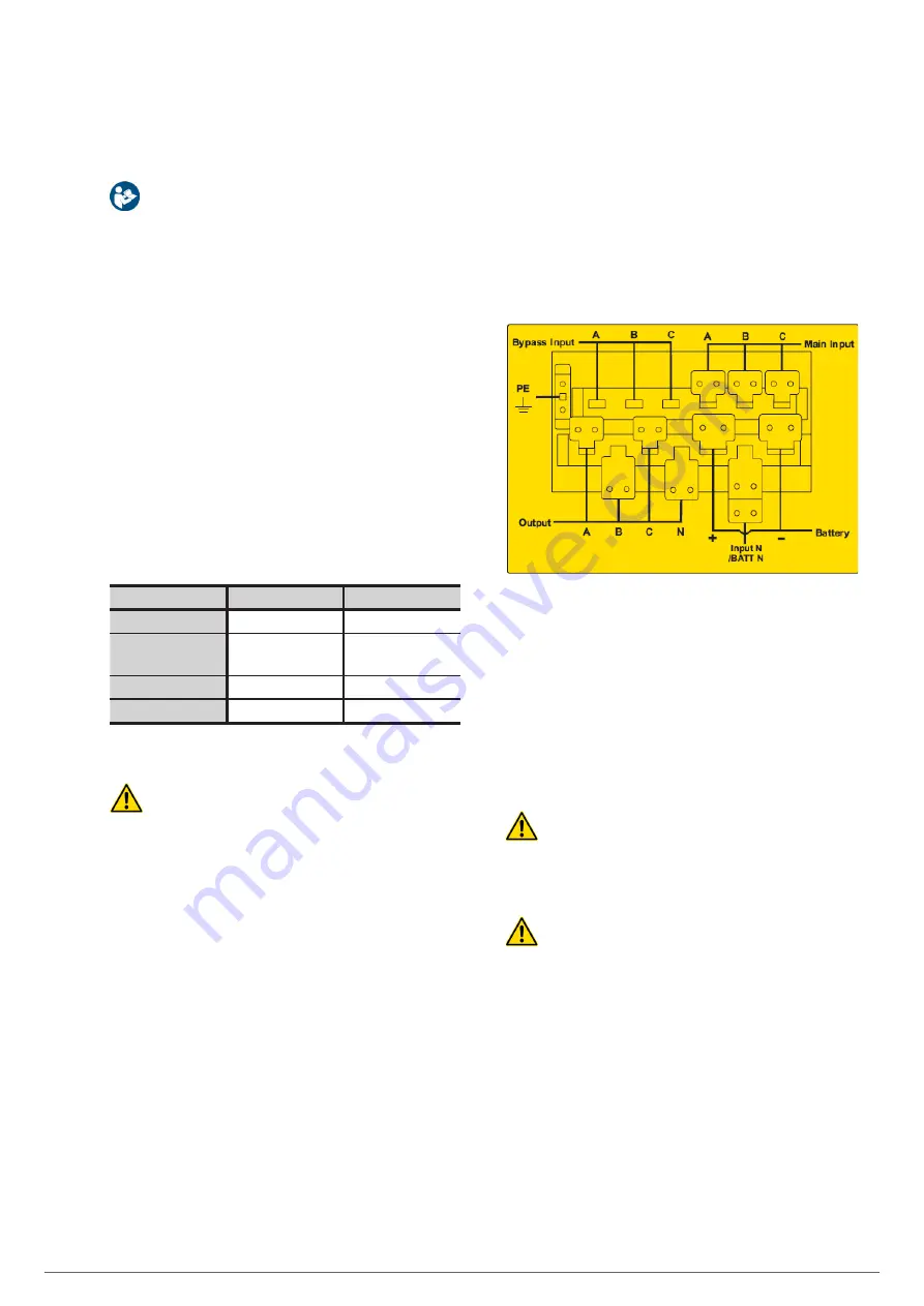
2.
Open the back door of the cabinet, remove the plastic cover.
The input and output terminal, battery terminal and protec-
tive earth terminal are shown in Fig. 23.
Fig. 23.
Connections terminals.
3.
Connect the protective earth wire to protective earth ter-
minal (PE).
4.
Connect the AC input supply cables to the Main Input ter-
minal and AC output supply cables to the Output terminal.
5.
Connect the Battery cables to the Battery terminal.
6.
Check to make sure there is no mistake and re-install all the
protective covers.
Attention :
The operations described in this section must be per-
formed by authorized electricians or qualified technical per-
sonnel. If you have any difficulties, contact the manufacturer
or agency.
Warning :
•
Tighten the connections terminals to enough torque mo-
ment, and please ensure correct phase rotation.
•
The grounding cable and neutral cable must be connected
in accordance with local and national codes.
ADAPT
UNINTERRUPTIBLE POWER SUPPLY
USER'S MANUAL