


17
Port
Name
Function
J5-1
+24V_DRY
+24V
J5-2
EXTERNAL_MAINT_
BYPASS
Aux. contact –NO-
external manual bypass
MCB
J5-3
GND_DRY
Power ground for +24V
Table 6.
Description of status interface and connection
of aux. contact external manual bypass MCB.
•
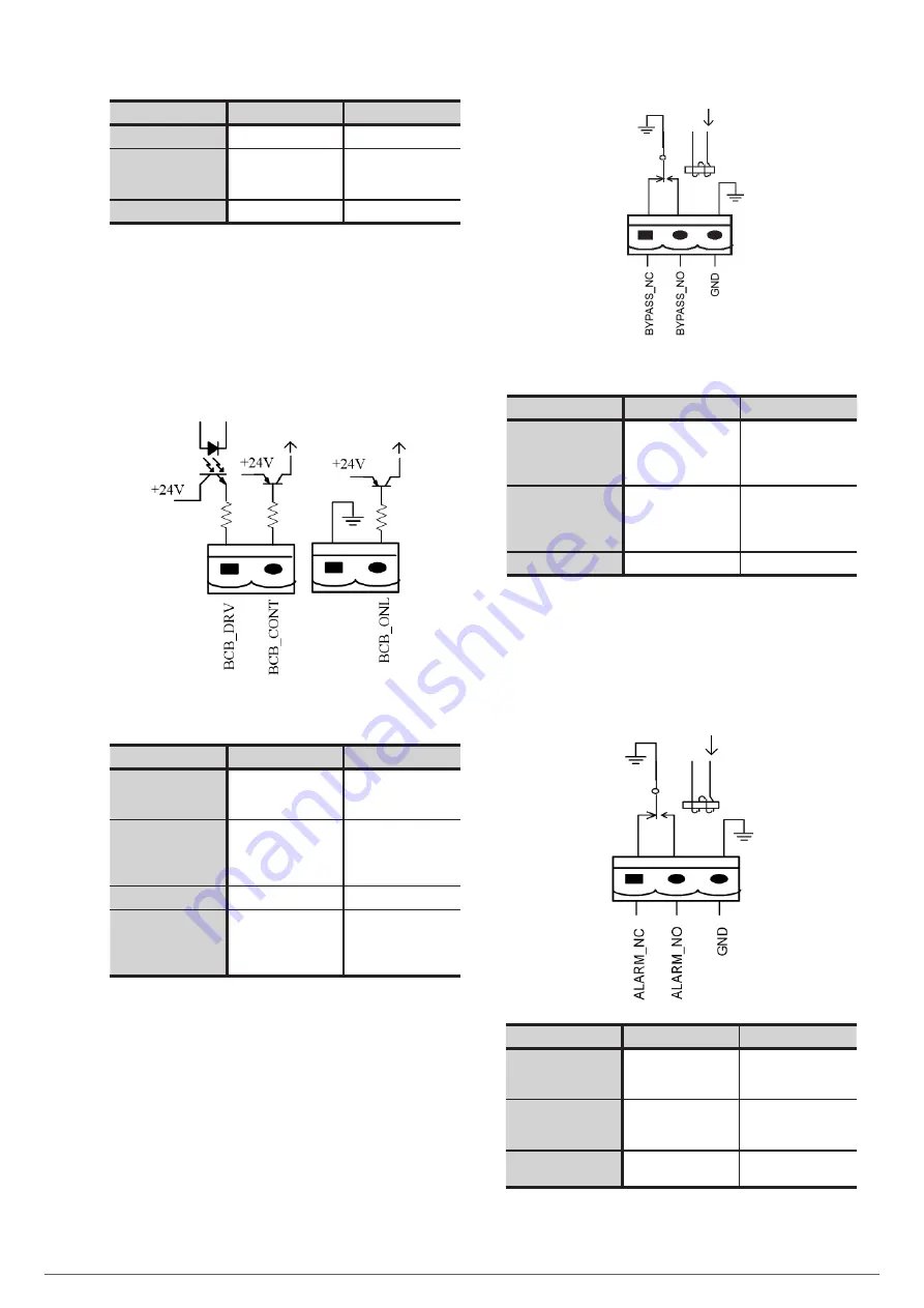
BCB Input Port
The default function of J6 and J7 are the ports of BCB. The
port diagram is shown in Fig. 28, and description is shown in
Table 7.
Fig. 28.
BCB Port.
Port
Name
Function
J6-1
BCB_DRIV
BCB contact drive,
pr24V voltage,
20mA drive signal
J6-2
BCB_Status
BCB contact status,
connect with the
normally open signal
of BCB
J7-1
GND_DRY
Power ground for +24V
J7-2
BCB_Online
BCB on-line input
(normally open), BCB is
on-line when the signal
is connecting with J7-1
Table 7.
Description of BCB port.
•
Bypass Output Dry Contact Interface .
The default function of J8 is the bypass output dry contact in-
terface. The interface diagram is shown in Fig. 29, and descrip-
tion is shown in Table 8.
Fig. 29.
Bypass dry contact interface diagram
Port
Name
Function
J8-1
BYPASS_ALARM_NC
Bypass relay (normally
closed). It will open
during the bypass
condition equipment.
J8-2
BYPASS _ALARM_NO
Bypass relay (normally
open). It will closed
during the bypass
condition equipment.
J8-3
BYPASS _ALARM_GND
Common terminal
Table 8.
Bypass dry contact interface description.
•
General Alarm Output Dry Contact Interface
The default function of J9 is the general alarm output dry contact
interface. When one or more warnings are triggered, an auxiliary
dry contact signal will be active via the isolation of a relay.
Port
Name
Function
J9-1
GENERAL_ALARM_NC Integrated warning relay
(normally closed) will be
open during warning
J9-2
GENERAL_ALARM_NO Integrated warning relay
(normally open) will be
closed during warning
J9-3
GENERAL_ALARM_
GND
Common terminal
Table 9.
General alarm dry contact interface description.
ADAPT
UNINTERRUPTIBLE POWER SUPPLY
USER'S MANUAL