RTR-4 Portable Digital X-Ray
Imaging System
Operator’s Manual
120300 Rev. D
15 February 2003
Page 1: ...RTR 4 Portable Digital X Ray Imaging System Operator s Manual 120300 Rev D 15 February 2003...
Page 2: ...its contents revealed in any manner to others without the express written permission of SAIC The recipient also agrees not to allow the use of this document by others without the express written conse...
Page 3: ...the limits for a Class A digital device pursuant to Part 15 of the FCC Rules These limits are designed to provide reasonable protection against harmful interference when the equipment is operated in a...
Page 4: ...tem to which this declaration relates is in conformance with the applicable provisions of the following directives 73 23 EEC governing product safety 89 336 EEC governing electromagnetic compatibility...
Page 5: ...ision B 28 February 2001 Wireless Option removed from Operator s Guide and transformed into a separate supplemental document Battery Charger chapter and CU 4 Modem chapter deleted C 20 October 2001 Mi...
Page 6: ...tion 3 1 RTR 4 System Standard Wired Configuration Components 3 1 Portable Notebook Controller 3 2 Integrated Imager 3 3 XR200 X Ray Source 3 8 Interconnecting Cables 3 8 Transport Case 3 9 RTR 4 Stan...
Page 7: ...ing an Image 4 25 Print an Image 4 25 Software Description 4 26 RTR 4 Functions 4 26 The Acquire Menu 4 27 The File Menu 4 31 The Display Menu 4 32 The Modify Menu 4 35 The Preferences Menu 4 39 The W...
Page 8: ...odel Imagers 5 10 Introduction 5 10 Standard View Imager 5 10 Alternate X Ray Sources 5 12 Introduction 5 12 Miscellaneous Accessories 5 13 Introduction 5 13 Wireless Option Backpack 5 13 Notebook PC...
Page 9: ...the equipment acquisition and processing of X ray images and some troubleshooting The information in this document is to be used only by technicians and operators who have been trained to use the RTR...
Page 10: ...Follow the instructions in the Golden operator s manual for repair of the Golden Engineering XR200 X ray source or visit their website at http www goldenengineering com Acronyms and Abbreviations The...
Page 11: ...al Authorization ROI Region Of Interest RTR Real Time Radiography SNR Signal to Noise Ratio tif Tagged Image Format a filename extension TLD Thermoluminescent Dosimeters Vac Volts alternating current...
Page 12: ...Introduction RTR 4 Operator s Manual 1 4 SAIC Proprietary 120300 Rev D...
Page 13: ...d Trained personnel only The RTR 4 should only be operated by technically qualified and trained personnel It is the responsibility of the RTR 4 user to ensure only trained personnel are permitted to c...
Page 14: ...e the potential for electrical shock may exist while performing a specific task The X Ray Radiation hazard warning symbol is used whenever emitted x ray radiation may exceed background levels during a...
Page 15: ...nel shall review and follow applicable regulations In order to meet the FCC RF safety regulations when using the wireless configuration personnel shall maintain a distance of at least 20cm 8in from th...
Page 16: ...onmental conditions affect the safe operating conditions of the RTR 4 Maximum external voltage fluctuation of 10 Maximum altitude 2000m 6562ft Operating temperature range 5 C 41 F to 40 C 104 F Maximu...
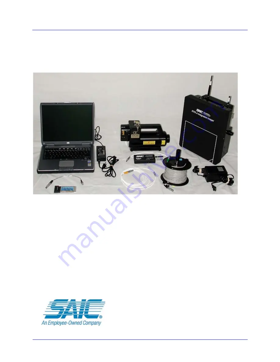
Page 17: ...ndard wired configuration and the standard wireless configuration only Alternate components are covered in later chapters Hardware Description RTR 4 System Standard Wired Configuration Components The...
Page 18: ...rovided to connect the PC modem RJ45 connector to the RTR 4 system cable reel when the system is setup in the wired configuration A WiFi Network Interface Card NIC is provided for connecting in the wi...
Page 19: ...ebook PC to ac power and provides 19Vdc to the PC for operation or internal battery charging Integrated Imager The Integrated Imager uses a compact solid state camera with a 20cm x 27cm 8 0in x 10 7in...
Page 20: ...Orientation Indicator A triangle in one corner of the image target area is shown as a ball in a circle on the controller PC image and indicates the lower edge of the image This ball is free floating...
Page 21: ...e adapter will charge the battery The Power On LED will indicate when the adapter is connected and the Battery Charge LED will indicate battery charge status Integrated Imager External Battery Charger...
Page 22: ...FAILURE battery is too hot or too cold for safe charging The battery should be brought to operating temperature On steady Green Off Red FAILURE battery is physically damaged do not use discard batter...
Page 23: ...mber when battery power is low Battery Charger LED Amber and flashing when testing battery Amber and on steady during battery charging Green and on steady when battery charging is complete Data Connec...
Page 24: ...d with a fully charged battery However this will vary with temperature battery age and source condition Standard features include Tube life 100 000 pulses X ray Source Power Key and spare 14 4Vdc remo...
Page 25: ...RTR 4 is protected during transport and storage by a rugged impact resistant plastic transport case with fitted foam inserts Key features are A single watertight crushproof foam lined case Dimensions...
Page 26: ...4 Wireless operation complies with the Hazards of Electromagnetic Radiation to Ordnance HERO specifications This consideration is only relevant if the RTR 4 is being used with potentially explosive d...
Page 27: ...rgy from the immediate area of the suspect package This cable connects from the radio module connector to the Imager at the receptacle located to the left of the radio module bulkhead connector Intern...
Page 28: ...its projected image and the larger its features appear in the acquired image This can be used to magnify small features but will result in fuzzier edges Objects that are closer to the imager more clo...
Page 29: ...moved from their transport cases All needed batteries have sufficient charge or have been recharged or replaced with new ones A cleared level workplace is available for setup and an appropriate exclus...
Page 30: ...ling if needed and available 6 Connect the 30cm 1ft adapter cable between the controller and the 50m 164ft cable reel 7 If 110 220Vac power is to be used for imager power connect the supplied external...
Page 31: ...ess configuration Prerequisites Verify the following prerequisites are completed before beginning this procedure The RTR 4 components have been removed from their transport cases All needed batteries...
Page 32: ...d Ensure antennas are mated to the proper connector and correctly aligned before tightening Do not force antennas onto connectors Failure to comply may damage equipment 3 Attach ANT 1 and ANT 2 to the...
Page 33: ...control panel 10 Turn on the Imager power switch 11 Using the key turn on the X ray source Verify that the X ray source s Exposure Selector display at the back of the X ray source handle is set to 99...
Page 34: ...ing an X Ray Image Description Follow this procedure to X ray an object Prerequisites Verify the following prerequisites are completed before beginning this procedure The RTR 4 is fully configured in...
Page 35: ...he number of pulses desired and the desired time delay 3 Press the Enter key or click on the Fire X Ray button The source fires and an image appears on the screen NOTE The X ray source fires and an im...
Page 36: ...System Description Setup and Quick Start RTR 4 Operator s Manual 3 20 SAIC Proprietary 120300 Rev D...
Page 37: ...ntenance Operating the RTR 4 Acquiring an X Ray Image Description Follow this procedure to X Ray an object Prerequisites Verify the following prerequisites are completed before beginning this procedur...
Page 38: ...r of pulses desired and the desired time delay 3 Press the Enter key or click on the Fire X Ray button The source fires and an image appears on the screen in the Original buffer NOTE The X Ray source...
Page 39: ...ollowing prerequisites are completed before beginning this procedure The RTR 4 is configured in accordance with the applicable setup procedure in the previous chapter The source and imager units are c...
Page 40: ...usion zone is clear of all personnel Failure to comply may result in personnel injury 4 Click the Fire and Sum X Ray button After the source fires an image appears on the screen along with the Fire an...
Page 41: ...nu 3 Verify the Multiple Originals command is disabled unchecked WARNING Excessive exposure to X Ray radiation is harmful Verify the exclusion zone is clear of all personnel Failure to comply may resu...
Page 42: ...he status bar 9 Select Add Images from the Modify menu The images are added together and the result appears in the Modified buffer 10 To make the image more visible click the Auto Contrast button on t...
Page 43: ...onfigured in accordance with the applicable setup procedures in the previous chapter The Safety Keyswitch has been turned 90 clockwise The RTR 4 imaging software has been properly configured and is in...
Page 44: ...unknown image file The image appears in the Modified buffer 9 Press the F7 key to display the Original Buffer Original appears in the status bar 10 Select Subtract Images for the Modify menu The resul...
Page 45: ...m for future reference Retrieving an Image Description Follow this procedure to open an image file from the images folder Prerequisites The RTR 4 imaging software has been properly configured and is l...
Page 46: ...rocedure RTR0009 Obtain image information as follows Using Multiple Image Display Description It is often useful to present images next to each other for comparison purposes Follow this procedure to s...
Page 47: ...ware has been properly configured and is loaded and running An image is displayed in the Original Buffer Procedure RTR 0011 Use the Grid Overlay feature as follows STEP ACTION 1 Select Multiple Origin...
Page 48: ...al buffer Procedure RTR0012 Measure distance as follows NOTE Once selected the Grid Overlay remains in place until cleared Complete step 3 to clear the Grid Overlay 3 Select Grid Overlay from the Disp...
Page 49: ...e RTR 4 imaging software has been properly configured and is loaded and running An image is displayed in the Original buffer Procedure RTR0013 Add lines and text to an image as follows STEP ACTION 1 T...
Page 50: ...just the brightness darkness and contrast of an image Prerequisites Verify the following prerequisites are completed before beginning this procedure The RTR 4 imaging software has been properly config...
Page 51: ...eft or right vertical blue bar will vary the brightness of the image Depending on the distribution of the density graph one may have more affect than the other The operator should try both until satis...
Page 52: ...ttes Description The default palette is grayscale Some images are easier to interpret if color is used to show density differences Follow this procedure to select the color palette or an inverted pale...
Page 53: ...nding the denser object These bright areas make it difficult to see the contents of the denser area Saturation Suppression changes the white pixels to black allowing better interpretation of detail in...
Page 54: ...been properly configured and is loaded and running An image is displayed in the Original buffer Procedure RTR0018 Sharpen an image as follows STEP ACTION 1 Select Saturation Suppression from the Displ...
Page 55: ...ed and is loaded and running An image is displayed in the Original buffer Procedure RTR0019 Smooth an image as follows 2 Or select Sharpen Fine Sharpen Moderate Sharpen Extreme from the Modify pull do...
Page 56: ...nning An image is displayed in the Original buffer Procedure RTR0020 Reduce image noise as follows 2 Select one of the following commands Smooth Fine Smooth Moderate Smooth Extreme from the Modify pul...
Page 57: ...his procedure The RTR 4 imaging software has been properly configured and is loaded and running An image is displayed in the Original buffer Procedure RTR0021 Edge detect an image as follows NOTE Nois...
Page 58: ...aging software has been properly configured and is loaded and running An image is displayed in the Original buffer Procedure RTR0022 Emboss an image as follows NOTE Edge Detect may only be used a few...
Page 59: ...re RTR0023 Use Histogram Equalize as follows Image Preservation The operator must be aware of the following regarding image preservation A newly acquired image is displayed in the Original buffer A ne...
Page 60: ...e default C Images folder with a default file name Prerequisites Verify an unsaved image is present in the active buffer Procedure RTR0024 QuickSave an image as follows ORIGINAL BUFFER BUFFER ACQUIRE...
Page 61: ...e as follows Print an Image Description Follow this procedure to print an image Prerequisites Verify the following prerequisites are completed before beginning this procedure STEP ACTION 1 Press the F...
Page 62: ...atures and commands are listed and described in the following paragraphs RTR 4 Functions In most cases the RTR 4 commands can be accessed by The pull down menus listed in the Main Menu bar at the top...
Page 63: ...image This information can then be retrieved viewed sorted by category and changed as needed to provide an accurate record of acquisitions and modifications and assist the user in locating and organi...
Page 64: ...lected the system waits the number of seconds specified in the Delay Timer field then the X Ray source fires for the specified number of pulses and an image is acquired Sum Used to collect an initial...
Page 65: ...t number of seconds Cancel may be selected to abort image acquisition at any point during the countdown Once the Delay Timer value has been changed it remains at the changed setting until the program...
Page 66: ...image Be sure the Contrast Stretch is set to Default before starting so the image does not wash out prematurely Disable Acquire The Disable Acquire command is depicted by button at the end of the too...
Page 67: ...F4 Select to store an image on the hard disk drive or a floppy disk under a user specified filename A dialog box is displayed on the screen select the desired location for the file and provide an appr...
Page 68: ...in the Display menu do not alter the data in the image they merely change the way the data is presented Exit Alt X When selected the RTR 4 imaging application is shut down All unsaved images are disca...
Page 69: ...of the objects The Inverted Rainbow option reverses the colors of the rainbow option Automatic Stretch F6 Select to adjust the brightness and contrast of the image automatically It selects settings th...
Page 70: ...show a dialog box displaying the date and time that the selected image was acquired Also shows the serial number of the Control Unit used to capture the image the number of pulses used to acquire the...
Page 71: ...n the Modified buffer If the modifications are not satisfactory press the F7 key to switch back to the Original buffer where the unmodified image may be changed in a different way If the displayed buf...
Page 72: ...sshair Click at one corner of the area to be modified and drag to the opposite corner and click again The ROI toolbar then appears Click on the desired toolbar button to modify the selected area Annot...
Page 73: ...lightly reduce the image resolution Fine slightly smooths noise edges and lines and is used for subtle adjustment Moderate smooths the image to a higher degree Extreme causes more smoothing for noisie...
Page 74: ...and to add images together to discern objects within dense containers or housings This feature is useful when the highest pulse rate setting 99 provides a dim image This feature allows the user to add...
Page 75: ...to make a nonlinear change to enhance subtle details in a different way than Auto Contrast It automatically adjusts the brightness of pixels to balance the number of pixels across the range of possibl...
Page 76: ...P ACTION 1 Select the Preferences pull down menu located at the top of the Main Screen 2 The Preferences pull down menu appears 3 Multiple Originals Select this command to utilize more buffers than th...
Page 77: ...s selection remains enabled after the RTR 4 imaging application is exited 9 Distance in Inches Select this command to display units in inches This selection remains enabled after the RTR 4 imaging app...
Page 78: ...mand to be prompted immediately after each acquired image to save the image The Save As dialog box will appear 15 Overpulse Protection Use this command to select one of the following No overpulse prot...
Page 79: ...ilable foreign languages may vary depending on the particular controller s OS 18 Enable Database Select this command to enable the database function and allow recording of ancillary data This option r...
Page 80: ...al layout pattern The Multiple Originals option under the Preferences menu must be enabled in order for more than two images to be displayed Arrange Icons Selecting this command reorganizes icons for...
Page 81: ...t COMMAND DESCRIPTION Help F10 When selected a help window containing the RTR 4 Operator Manual appears The first image is the index to chapters with hypertext links where the text is underlined Click...
Page 82: ...mand are listed together The Esc key can be used to cancel any command request MENU COMMAND FUNCTION KEY TOOLBAR BUTTON Acquire F1 Quick Save F2 Open F3 Save As F4 Print Ctrl P n a Exit Alt X n a Zoom...
Page 83: ...ev D SAIC Proprietary 4 47 Distance Measurement Ctrl D n a Switch Buffers F7 Undo Ctrl Z Redo Ctrl Y ROI Processing n a Sharpen Moderate F8 Smooth Moderate F9 Help F10 Acquire Disable n a Key Map Ctrl...
Page 84: ...enabled by checking Enable Database on the Preferences menu When the Enable Database option is unchecked the software operates without the ability to append related data to displayed images When the...
Page 85: ...y have many associated files appended to the image Incidents and their associated files can be exported to archive the data outside of the RTR 4 system Pre existing incident files can be imported to a...
Page 86: ...the entries will create a new incident The incident name and description fields accept typed input from the operator The user and location fields will accept typed in data or the operator can select...
Page 87: ...Proprietary 4 51 clicks on OK to save the image These values are provided by the system or the user specified defaults The user can specify the defaults for the Save Image Data dialog box by using th...
Page 88: ...database with a sign by each incident name Clicking on this sign expands the entry showing the RTR 4 X ray images appended to that incident The appended files are displayed in a smaller window below...
Page 89: ...or can enter search data for specific incidents and related data The query window provides the operator with several methods to locate specific incident information The operator can search on Incident...
Page 90: ...e operator to change the entries for the Save Image Data dialog box This is the window that is displayed when saving an image Modify Associated Data The Modify Associated Data Screen allows the operat...
Page 91: ...This allows the operator to save or combine incidents Selecting the Export option causes a query style window to appear The operator selects an incident by clicking on the box to the left of the incid...
Page 92: ...nfiguration only Prerequisites There are no prerequisites for this procedure Procedure RTR0028 Shutdown and stow the RTR 4 as follows STEP ACTION 1 Exit the RTR 4 imaging software 2 At the Windows des...
Page 93: ...mild detergent but care must be taken to prevent water from seeping inside any of 7 At the X ray source turn the keyswitch counterclockwise 90 to the off position 8b At the imager disconnect the comm...
Page 94: ...ower source Batteries should be disconnected from the charging once they are fully charged Charging the Source Battery The source battery is charged on an external battery charger Remove the battery f...
Page 95: ...ntegrated Imager unit Prerequisites Verify all power is off and the Imager is not connected to other RTR 4 components or to external power Procedure RTR0029 Replace the battery as follows STEP ACTION...
Page 96: ...nal X Ray Receiver is turned off Procedure RTR0030 Replace the 9V battery as follows NOTE The battery compartment cover will not close properly if the battery was replaced facing the wrong way If cove...
Page 97: ...al strength in the connection between the WiFi NIC and Integrated Imager radio module Follow this procedure to determine the set s signal to noise ratio SNR when deployed in the field Prerequisites En...
Page 98: ...n the Windows desktop or select Programs Orinoco WaveMANAGER CLIENT from the Start menu A dialog box entitled WaveManager Client Status Functions appears For Windows XP OS Select Programs Orinoco Clie...
Page 99: ...b The Windows 98 and Windows XP Operating System dialog boxes are slightly different but their functionality is identical 3 Select the Test Results tab to display a horizontal real time connectivity b...
Page 100: ...ay a real time signal to noise ratio SNR figure and corresponding line graphs 5 Click the Cancel button on either the Test Results or Test History dialog boxes to exit the tests 6 Click the Close butt...
Page 101: ...s manual This chapter consists of the following sections Previous Model Wireless Option Previous Model Controllers Previous Model Imagers Alternate X ray Sources Miscellaneous Accessories Previous Mod...
Page 102: ...he Power Transceiver unit has three functions Provides power to the imager previously supplied by the controller in the CU 4 case or the external power supply in the notebook case Facilitates wireless...
Page 103: ...have a red LED later versions have a green LED Radio frequency communications between the Imager and the Controller combined with the radio frequency communications with the X ray Source Receiver are...
Page 104: ...ller Notebook Controller with Battery Box Standard CU 4 Components The standard CU 4 controller unit is a fully integrated computer comprised of the following components Pentium series processor Flat...
Page 105: ...y switch B Color display C Battery charge indicator light D Hard drive LED indicates that the hard disk drive is in use E Power LED indicates that controller power is on F Standby LED indicates that t...
Page 106: ...ceptacle for external DC power 9 5 to 28 Vdc F Serial Port COM1 for external mouse keypad X ray source control etc G External monitor connector AUX VGA for use with an external monitor to display imag...
Page 107: ...er saving feature that darkens the computer screen if not used for two to four minutes Pressing the shift key or moving the mouse reactivates the screen from the power saver mode Do not press any othe...
Page 108: ...rd line power source An optional external battery charger can charge optional spare batteries Fully recharging a discharged battery with an external charger takes about three hours A red LED on the CU...
Page 109: ...ook controller has a Battery Box that is necessary to power the Standard View Imager and also routes communication and image data signals between the Imager and the Notebook Control Unit This unit hou...
Page 110: ...ted with 9 pin plugs on either end One side connects to the Interlock Key Box and the other is plugged into the COM port on the rear panel of the Notebook Controller This connection is required so tha...
Page 111: ...tline on the flat side of the Imager unit The X ray source unit should be positioned approximately 60 90cm 24 35in from the Imager with its beam centered on and perpendicular to the Imager face The tw...
Page 112: ...y Source unit s beam to be properly centered on the screen Imager Unit with Elevated Source Alternate X Ray Sources Introduction The RTR 4 can currently be used with the following Golden Engineering X...
Page 113: ...R 4 wireless option backpack provides a compact convenient way of moving and operating the RTR 4 Wireless Option configuration The backpack holds the following items the imager unit the X ray source u...
Page 114: ...table lists and describes the optional accessories for the standard RTR 4 Notebook configuration ITEM DESCRIPTION Notebook Safety Lock An optional safety lock in a small box can be connected between t...
Page 115: ...Safety 2 3 Grid Overlay 4 11 H Help menu 4 44 Histogram Equalize 4 23 I Icon toolbar 4 45 Image Data 4 50 Image information 4 10 Image preservation 4 23 Image Processing 4 9 Image saturation 4 17 Imag...
Page 116: ...ge 4 25 Save Image Data 4 54 Save the image 4 51 Search data 4 53 Set Default Values 4 51 4 55 Setup wired configuration 3 13 Setup wireless configuration 3 15 Sharpen an image 4 18 Show multiple imag...