Rosemount 8712 Reference Manual Download Page 126

Reference Manual

00809-0100-4664, Rev BA

January 2010

Rosemount 8712

B-2

Canadian Standards Association (CSA)
N0

Non-incendive for Class I, Division 2, Groups A, B, C, and D non-flammable fluids (T4 at 40 
°C), and Dust-ignition proof Class II/III, Division 1, Groups E, F, and G (T4 at 40 °C) 
Hazardous locations; Enclosure Type 4X

European Certifications

N1

ATEX Type n
ATEX Certificate No: BASEEFA 05ATEX0170X
EEx nA nL IIC T4 (Ta = -40 °C to + 60 °C)
V

max 

= 42 V DC

 0575

Special Conditions for Safe Use (x)

The apparatus is not capable of withstanding the 500V insulation test required by Clause 
8.1of EN 60079-15: 2003. This must be taken into account when installing the apparatus.

International Certifications

IECEx
N7

IECEx Type n
Certificate No: IECEx BAS 07.0036X
Ex nA nL IIC T4 (Ta = -40 °C to + 60 °C)
V

max 

= 42 V DC

Special Conditions for Safe Use (x)

The apparatus is not capable of withstanding the 500V insulation test required by Clause 
6.8.1of IEC 60079-15: 2005. This must be taken into account when installing the apparatus.
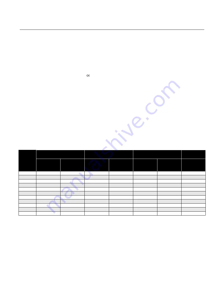
Sensor Approval 
Information

Approval 

Codes

Rosemount 8705 Sensor

Rosemount 8707 Sensor

Rosemount 8711 Sensor

Rosemount 8721

Sensors

For 

Non-flammable 

Fluids

For Flammable 

Fluids

For 

Non-flammable 

Fluids

For Flammable 

Fluids

For 

Non-flammable 

Fluids

For Flammable 

Fluids

For 

Non-flammable 

Fluids

NA

N0

ND

N1

N5

N7

ND

NF

E1

E5

(1)

KD

(2)

(1) Available in line sizes up to 8 in. (200 mm) only.
(2) Refer to Table B-2 on page B-4 
for relation between ambient temperature, process temperature, and temperature class.

Summary of Contents for 8712

Page 1: ...www rosemount com Reference Manual 00809 0100 4664 Rev BA January 2010 Rosemount 8712 Remote Mount Magnetic Flowmeter System ...

Page 2: ......

Page 3: ...ted questions United States 1 800 999 9307 7 00 am to 7 00 pm CST Asia Pacific 65 777 8211 Europe Middle East Africa 49 8153 9390 North American Response Center Equipment service needs 1 800 654 7768 24 hours includes Canada Outside of these areas contact your local Emerson Process Management representative The products described in this document are NOT designed for nuclear qualified applications...

Page 4: ......

Page 5: ...ions Considerations and Procedures 2 9 Connect Transmitter Power 2 9 Connect 4 20 mA Loop External Power Source 2 9 Connect Pulse Output Power Source 2 10 Connect Auxiliary Channel 1 2 11 Connect Auxiliary Channel 2 2 12 sensor Connections 2 13 Rosemount Sensors 2 13 Transmitter to Sensor Wiring 2 13 Conduit Cables 2 14 Sensor to Remote Mount Transmitter Connections 2 15 SECTION 3 Configuration In...

Page 6: ...Setup 4 16 Additional Parameters 4 16 Configure Outputs 4 17 LOI Configuration 4 31 Signal Processing 4 31 Universal Auto Trim 4 34 Device Info 4 34 SECTION 5 Sensor Installation Safety Messages 5 1 Sensor Handling 5 3 Sensor Mounting 5 4 Upstream Downstream Piping 5 4 Sensor Orientation 5 4 Flow Direction 5 6 Installation Flanged Sensor 5 7 Gaskets 5 7 Flange Bolts 5 7 Installation Wafer Sensor 5...

Page 7: ...y C 1 Licensing and Enabling C 2 Licensing the 8712 Diagnostics C 2 Tunable Empty Pipe Detection C 2 Tunable Empty Pipe Parameters C 3 Optimizing Tunable Empty Pipe C 3 Troubleshooting Empty Pipe C 4 Ground Wiring Fault Detection C 4 Ground Wiring Fault Parameters C 4 Troubleshooting Ground Wiring Fault C 5 Ground Wiring Fault Functionality C 5 High Process Noise Detection C 5 High Process Noise P...

Page 8: ... 22 Kent Sensors E 28 Krohne Sensors E 30 Siemens Sensors E 33 Taylor Sensors E 34 Toshiba Sensors E 36 Yamatake Honeywell Sensors E 37 Yokogawa Sensors E 38 Generic Manufacturer Sensors E 39 APPENDIX F HART Field Communicator Operation HandHeld Communicator F 1 Connections and Hardware F 2 Basic Features F 3 Action Keys F 3 Alphanumeric and Shift Keys F 4 Fast Key Feature F 5 Menus and Functions ...

Page 9: ...ransmitters Rosemount 8712 Rosemount 8732 The sensor is installed in line with process piping either vertically or horizontally Coils located on opposite sides of the sensor create a magnetic field Electrodes located perpendicular to the coils make contact with the process fluid A conductive liquid moving through the magnetic field generates a voltage at the two electrodes that is proportional to ...

Page 10: ...uthorization RMA number The center will also ask for the name of the process material to which the product was last exposed Mishandling products exposed to a hazardous substance may result in death or serious injury If the product being returned was exposed to a hazardous substance as defined by OSHA a copy of the required Material Safety Data Sheet MSDS for each hazardous substance identified mus...

Page 11: ...symbol is used throughout this manual to indicate that special attention to warning information is required Instructions and procedures in this section may require special precautions to ensure the safety of the personnel performing the operations Please refer to the following safety messages before performing any operation in this section Failure to follow these installation guidelines could resu...

Page 12: ...losive environment must be in accordance with the appropriate local national and international standards codes and practices Please review the approvals section of the 8712 reference manual for any restrictions associated with a safe installation Before connecting a handheld communicator in an explosive atmosphere make sure the instruments in the loop are installed in accordance with intrinsically...

Page 13: ...t 8712 Figure 2 1 Rosemount 8712 Dimensional Drawing 4 31 109 LOI Keypad Cover 9 01 229 11 15 283 2 81 71 3 11 79 12 02 305 0 44 11 Ground Lug 1 2 14 NPT Conduit Connection 4 Places WITH STANDARD COVER NOTE Dimensions are in inches millimeters 2 96 75 WITH LOI COVER ...

Page 14: ...he mounting plate to the pipe using the mounting hardware 2 Attach the 8712 to the mounting plate using the mounting screws Surface Mounting To surface mount the transmitter 1 Attach the 8712 to the mounting location using the mounting screws Identify Options and Configurations The standard application of the 8712 includes a 4 20 mA output and control of the sensor coils Other applications may req...

Page 15: ...power see Connect 4 20 mA Loop External Power Source on page 2 9 Transmitter Security The security switch on the 8712 allows the user to lock out any configuration changes attempted on the transmitter No changes to the configuration are allowed when the switch is in the ON position The flow rate indication and totalizer functions remain active at all times With the switch in the ON position you ma...

Page 16: ...tric gel can be used to pot the sensor terminal block Example 2 Installing flowmeters into explosion proof flameproof areas Conduit connections and conduit must be rated for use in the hazardous area to maintain flowmeter approval rating Conduit Cables Run the appropriate size cable through the conduit connections in your magnetic flowmeter system Run the power cable from the power source to the t...

Page 17: ...ker and locate it near the transmitter Requirements for 90 250 V AC Power Supply Wire the transmitter according to local electrical requirements for the supply voltage In addition follow the supply wire and disconnect requirements on page 2 9 Requirements for 12 42 V DC Power Supply Units powered with 12 42 V DC may draw up to 1 amp of current As a result the input power wire must meet certain gau...

Page 18: ...241 683 996 304 62 19 14 0 002525 0 008282 5941 1811 3564 1087 1584 483 99 30 12 0 001588 0 005209 9446 2880 5668 1728 2519 768 157 48 10 0 000999 0 003277 15015 4578 9009 2747 4004 1221 250 76 Types of Power Supply Wires Maximum Length of the Wire for Each Corresponding Power Supply Source Wire Gauge Annealed Cu milliohms ft milliohms m 42 V DC Supply ft m 30 V DC Supply ft m 20 V DC Supply ft m ...

Page 19: ...uirements outlined on page 2 8 2 Turn off the power source 3 Open the power terminal cover 4 Run the power cable through the conduit to the transmitter 5 Loosen the terminal guard for terminals L1 and N 6 Connect the power cable leads as shown in Figure 2 5 a Connect AC Neutral or DC to terminal N b Connect AC Line or DC to terminal L1 c Connect AC Ground or DC Ground to the ground screw mounted o...

Page 20: ...ce and connecting cable meet the requirements outlined above and in Electrical Considerations on page 2 7 2 Turn off the transmitter and analog power sources 3 Run the power cable into the transmitter 4 Connect DC to Terminal 8 5 Connect DC to Terminal 7 Refer to Figure 2 6 on page 2 10 Figure 2 6 4 20 mA Loop Power Connections Connect Pulse Output Power Source The pulse output function provides a...

Page 21: ... Electromechanical Totalizer Counter Figure 2 8 Connecting to a Electronic Totalizer Counter without Integral Power Supply Connect Auxiliary Channel 1 Auxiliary channel 1 can be configured as either a digital input or a digital output When configured as an input the following requirements apply When using channel 1 as a digital input the power source and the control relay must be connected to the ...

Page 22: ...elay or Input to Control System Connect Auxiliary Channel 2 Auxiliary channel 2 is configured to provide a digital output based on the configuration parameters set in the transmitter The following requirements apply to this channel When connecting power to channel 2 complete the following steps 1 Ensure that the power source and connecting cable meet the requirements outlined previously 2 Turn off...

Page 23: ...es 4 13 4 14 4 15 and 4 16 Either one may be used for both the coil drive and electrode cables Use the stainless steel plug that is provided to seal the unused conduit port A single dedicated conduit run for the coil drive and electrode cables is needed between a sensor and a remote transmitter Bundled cables in a single conduit are likely to create interference and noise problems in your system U...

Page 24: ...e the ends of the coil drive and electrode cables as shown in Figure 2 12 Limit the unshielded wire length to 1 inch on both the electrode and coil drive cables NOTE Excessive lead length or failure to connect cable shields can create electrical noise resulting in unstable meter readings Figure 2 12 Cable Preparation Detail Table 2 3 Cable Requirements Description Units Part Number Signal Cable 20...

Page 25: ... Connect coil drive and electrode cables as shown in Figure 2 13 Do not connect AC power to the sensor or to terminals 1 and 2 of the transmitter or replacement of the electronics board will be necessary Figure 2 13 Wiring Diagram Rosemount 8712 Transmitter Rosemount 8705 8707 8711 8721 sensors 1 1 2 2 17 17 18 18 19 19 ...

Page 26: ...Reference Manual 00809 0100 4664 Rev BA January 2010 Rosemount 8712 2 16 ...

Page 27: ...r Wiring Diagrams on page E 1 The Rosemount 8712 features a full range of software functions for configuration of output from the transmitter Software functions are accessed through the LOI AMS a Handheld Communicator or a control system Configuration variables may be changed at any time and specific instructions are provided through on screen instructions INSTALLATION CHECK AND GUIDE Use this gui...

Page 28: ...er grounding will cause erratic operation of the system Wiring 1 The signal wire and coil drive wire must be twisted shielded cable Emerson Process Management Rosemount division recommends 20 AWG twisted shielded cable for the electrodes and 14 AWG twisted shielded cable for the coils 2 The cable shield must be connected at both ends of the electrode and coil drive cables Connection of the shield ...

Page 29: ... transmitter parameters and stepped access to the advanced functions of the 8712 through the AUX FUNCTION key Figure 3 1 Local Operator Interface Keypad Data Entry The LOI keypad does not have numerical keys Numerical data is entered by the following procedure 1 Access the appropriate function 2 Use SHIFT to highlight the digit you want to enter or change 3 Use INCR to change the highlighted value...

Page 30: ...e Select Value Example Changing the ANALOG OUTPUT RANGE 1 Press ANALOG OUTPUT RANGE 2 Press SHIFT to position the cursor 3 Press INCR to set the number 4 Repeat steps 2 and 3 until desired number is displayed 5 Press ENTER After a moment the LCD will display the new analog output range Table 3 2 LOI Data Entry Keys and Functions Data Entry Keys Function Performed Shift Moves the blinking cursor on...

Page 31: ...ic Normal or Filter 5 or 37 Hz Flow Span Flow Totalize Span Totalize Forward Reverse or Net Gross Configure the totalizer units of measure On Off Volume units base volume units conversion time base rate units Required for units of mass flow Configure Auxiliary Channel 1 Configure Auxiliary Channel 2 Configure Flow Limit 1 Alert Configure Flow Limit 2 Alert Configure Totalizer Limit Alert Configure...

Page 32: ... your needs and the configuration of your flowmeter When commissioning a flowmeter review each process variable its function and output and take corrective action if necessary before using the flowmeter in a process application Process Variable PV The actual measured flow rate in the line Use the Process Variable Units function to select the units for your application Percent of Range The process ...

Page 33: ...r was last reset NOTE To reset the measured gross total value the line size must be changed Measured Net Total Measured net total provides the output reading of the totalizer This value is the amount of process fluid that has passed through the flowmeter since the totalizer was last reset When reverse flow is enabled the net total represents the difference between the total flow in the forward dir...

Page 34: ...semount 8712 must be set for all applications of the transmitter in a magnetic flowmeter system If your application requires the advanced functionality features of the Rosemount 8712 see Section 4 Operation of this manual Tag Tag is the quickest and shortest way of identifying and distinguishing between transmitters Transmitters can be tagged according to the requirements of your application The t...

Page 35: ... For example if the desired special units are cubic cm min the special volume variable can be represented as cc or cm3 The volume units variable is also used in totalizing the special units flow ft sec B31 sec 1 Barrel 31 5 gallons m sec B31 min 1 Barrel 31 5 gallons gal sec B31 hr 1 Barrel 31 5 gallons gal min B31 day 1 Barrel 31 5 gallons gal hr lbs sec gal day lbs min l sec lbs hr l min lbs day...

Page 36: ...s the units format for your primary variable The actual special units setting you define will not appear Four characters are available to store the new units designation The 8712 LOI will display the four character designation as configured Example To display flow in cubic cm per minute and one cm3 is equal to 0 001 liters the procedure would be Set the Volume Unit to cm3 or cc Set the Base Volume...

Page 37: ...r to configuration of URV and LRV PV LRV Lower Range Value Set the lower range value LRV or analog output zero to change the size of the range or span between the URV and LRV Under normal circumstances the LRV should be set to a value near the minimum expected flow rate to maximize resolution The LRV must be between 39 3 ft s to 39 3 ft s 12 m s to 12 m s NOTE Line size special units and density m...

Page 38: ...git calibration number exists for your sensor NOTE Be sure the calibration number reflects a calibration to a Rosemount reference transmitter If the calibration number was generated by a means other than a certified Rosemount flow lab accuracy of the system may be compromised If your sensor is not a Rosemount sensor and was not calibrated at the Rosemount factory contact your Rosemount representat...

Page 39: ...perly to assist in troubleshooting to identify potential causes of error messages and to verify the health of the transmitter and sensor Diagnostic tests can be initiated through the use of a HART based communications device the Local Operator Interface or through the control system Rosemount offers several different diagnostic suites providing various functionality Standard diagnostics included w...

Page 40: ...stics menu contains all of the standard diagnostics and tests that are available in the 8712 transmitter Self Test The transmitter test initiates a series of diagnostic tests that are not performed continuously during normal operation It performs the following tests Display Test RAM Test PROM Test During the entire test all outputs respond to flow signal The test requires about ten seconds to comp...

Page 41: ...ed pulse output level set by the transmitter On the LOI the test will end after five minutes if the transmitter is not returned to normal operation manually Select Value Set the value of the pulse output for the test to a value between 1 pulse day to 10 000 Hz End This command cancels the pulse output loop test and returns the pulse output back into normal operating mode Tune Empty Pipe Empty Pipe...

Page 42: ... This functionality can be used for operating simple batching operations or generating alerts when certain flow conditions are met This parameter can be configured as a discrete output if the transmitter was ordered with auxiliary outputs enabled option code AX or if this functionality has been licensed in the field Control 1 Turns the Flow Limit 1 ON or OFF ON The transmitter will generate a HART...

Page 43: ...w conditions are met This parameter can be configured as a discrete output if the transmitter was ordered with auxiliary outputs enabled option code AX or if this functionality has been licensed in the field If a digital output is configured for Flow Limit 1 the digital output will activate when the conditions for mode 1 are met Control 2 Turns the Flow Limit 2 HART Alert ON or OFF ON The transmit...

Page 44: ...transmitter was ordered with auxiliary outputs enabled option code AX or if this functionality has been licensed in the field Total Control Turns the Total Limit HART Alert ON or OFF ON The transmitter will generate a HART alert when the defined conditions are met OFF The transmitter will not generate a HART alert for the Total Limit Total Mode Mode that determines when the Total Limit HART Alert ...

Page 45: ...nced diagnostics suite option two DA2 option contains advanced diagnostics for the 8714i Meter Verification This diagnostic is used to verify the accuracy and performance of the magnetic flowmeter installation 8714i Meter Verification This diagnostic allows you to test and verify that the sensor transmitter or both are working within specifications For more details on this diagnostic see Appendix ...

Page 46: ...is parameter see Appendix C Diagnostics Actual Velocity Displays the velocity measured by the transmitter during the transmitter calibration verification test For more details on this parameter see Appendix C Diagnostics Velocity Deviation Displays the deviation of the transmitter calibration verification test For more details on this parameter see Appendix C Diagnostics Transmitter Calibration Te...

Page 47: ...x C Diagnostics Signature Values Review the current values stored for the sensor signature For more details on this parameter see Appendix C Diagnostics Coil Resistance View the base line value for the coil resistance taken during the sensor signature process Coil Signature View the base line value for the coil signature taken during the sensor signature process Electrode Resistance View the base ...

Page 48: ...ria for the 8714i Meter Verification test at Full Pipe No Flow conditions Flowing Limit 1 to 10 percent Set the pass fail test criteria for the 8714i Meter Verification test at Full Pipe Flowing conditions Empty Pipe Limit 1 to 10 percent Set the pass fail test criteria for the 8714i Meter Verification test at Empty Pipe conditions Measurements View the measured values taken during the meter verif...

Page 49: ... what capabilities have been licensed and are available for activation License Key A license key is required to activate features in the field if the desired functionality was not initially ordered This menu allows for gathering of necessary data to generate a license key and also the ability to enter the license key once it has been received Device ID This function displays the Device ID and Soft...

Page 50: ...e High Process Noise alert to activate 37 Hz Signal to Noise Ratio Read the current value of the signal to noise ratio at 37 5 Hz For optimum performance a value greater than 50 is preferred Values less than 25 will cause the High Process Noise alert to activate Signal Power Read the current value of the velocity of the fluid through the sensor Higher velocities result in greater signal power 8714...

Page 51: ...il For more details on this parameter see Appendix C Diagnostics Sensor Verification Deviation Displays the deviation of the sensor calibration verification test For more details on this parameter see Appendix C Diagnostics Sensor Verification Result Displays the result of the sensor calibration verification test as pass or fail For more details on this parameter see Appendix C Diagnostics Coil Ci...

Page 52: ...here calibration values are entered in units of milliamperes Scaled D A trimming allows you to trim the flowmeter using a scale that may be more convenient based upon your method of measurement For example it may be more convenient for you to make current measurements by direct voltage readings across the loop resistor If your loop resistor is 500 ohms and you want to calibrate the meter using vol...

Page 53: ...semount 8714D Calibration Standard connected and read the flow rate The electronics need about a 5 minute warm up time to stabilize 4 Set the 8714D Calibration Standard to the 30 ft s 9 1 m s setting 5 The flow rate reading after warm up should be between 29 97 9 1 m s and 30 03 ft s 9 2 m s 6 If the reading is within the range return the transmitter to the original configuration parameters 7 If t...

Page 54: ...nsmitter If there are any alerts or error messages that have activated they will be listed here ADVANCED CONFIGURATION In addition to the basic configuration options and the diagnostic information and controls the 8712 has many advanced functions that can also be configured as required by the application DETAILED SETUP The detailed setup function provides access to other parameters within the tran...

Page 55: ...pulse auxiliary and totalizer outputs of the transmitter Analog Output Under this function the advanced features of the analog output can be configured PV Upper Range Value URV The upper range value URV or analog output range is preset to 30 ft s at the factory The units that appear will be the same as those selected under the units parameter The URV 20 mA point can be set for both forward or reve...

Page 56: ...eater than the LRV the analog output will saturate at 3 9 mA when the flow rate falls below the selected 4 mA point The minimum allowable span between the URV and LRV is 1 ft s Do not set the LRV within 1 ft s 0 3 m s of the 20 mA point For example if the URV is set to 15 67 ft s 4 8 m s and if the desired URV is greater than the LRV then the highest allowable analog zero setting would be 14 67 ft...

Page 57: ...he 4 20 mA trim is now completed You may repeat the 4 20 mA trim to check the results or use the analog output test Scaled D A Trim Scaled D A trim enables you to calibrate the flowmeter analog output using a different scale than the standard 4 20 mA output scale Non scaled D A trimming described above is typically performed using an ammeter where calibration values are entered in units of milliam...

Page 58: ...d been chosen when selecting the flow rate unit the volume unit displayed would be gallons NOTE The pulse output scaling is designed to operate between 0 and 10 000 Hz The minimum conversion factor value is found by dividing the minimum span in units of volume per second by 10 000 Hz When selecting pulse output scaling remember that the maximum pulse rate is 10 000 Hz With the 110 percent overrang...

Page 59: ...0 Hz it is recommended to set the pulse mode to 50 duty cycle If the pulse width is set too wide more than 1 2 the period of the pulse the transmitter will automatically default to a pulse width of 50 duty cycle Figure 4 1 Pulse Output Example If pulse width is set to 100 ms the maximum output is 5 Hz for a pulse width of 0 5 ms the maximum output would be 1000 Hz at the maximum frequency output t...

Page 60: ...le Example The external counter is ranged for 350 gpm and pulse is set for one gallon Assuming the pulse width is 0 5 ms the maximum frequency output is 5 833 Hz Example The upper range value 20 mA is 3000 gpm To obtain the highest resolution of the pulse output 10 000 Hz is scaled to the full scale analog reading Pulse Scaling Flow Rate gpm 60 s min Frequency Pulse Scaling 10 000 gpm 60 s min 10 ...

Page 61: ... When conditions are met to activate the input the transmitter will force the output to zero flow Net Total Reset When conditions are met to activate the input the transmitter will reset the Net Total value to zero Output Channel 1 will be configured as a discrete output Options are Reverse Flow The output will activate when the transmitter detects a reverse flow condition Zero Flow The output wil...

Page 62: ...activate when the transmitter measures a flow rate that meets the conditions established for the Flow Limit 1 Alert Flow Limit 2 The output will activate when the transmitter measures a flow rate that meets the conditions established for the Flow Limit 2 Alert Diagnostic Status Alert The output will activate when the transmitter detects a condition that meets the configured criteria of the Diagnos...

Page 63: ...ds to the high limit set point for the Flow Limit 1 alert Low Limit 1 Set the flow rate value that corresponds to the low limit set point for the Flow Limit 1 alert Flow Limit Hysteresis Set the hysteresis band for the flow limit to determine how quickly the transmitter comes out of Alert status This hysteresis value is used for both Flow Limit 1 and Flow Limit 2 Flow Limit 2 Configure the Paramet...

Page 64: ...for the Flow Limit 2 alert Low Limit 2 Set the flow rate value that corresponds to the low limit set point for the Flow Limit 2 alert Flow Limit Hysteresis Set the hysteresis band for the flow limit to determine how quickly the transmitter comes out of Alert status This hysteresis value is used for both Flow Limit 1 and Flow Limit 2 Total Limit Configure the Parameters that will determine the crit...

Page 65: ...otal Limit Hysteresis Set the hysteresis band for the total limit to determine how quickly the transmitter comes out of Alert status Diagnostic Status Alert Turn ON OFF the diagnostics that will cause this Alert to activate ON The Diagnostic Status Alert will activate when a transmitter detects a diagnostic designated as ON OFF The Diagnostic Status Alert will not activate when diagnostics designa...

Page 66: ...e Total Measured reverse total provides the output reading of the totalizer This value is the amount of process fluid that has passed through the flowmeter in the reverse direction since the totalizer was last reset This value is only totalized when reverse flow is enabled Start Totalizer Start totalizer starts the totalizer counting from its current value Stop Totalizer Stop totalizer interrupts ...

Page 67: ...nsmitters can be accomplished with commercially available Bell 202 modems and a host implementing the HART protocol Each transmitter is identified by a unique address 1 15 and responds to the commands defined in the HART protocol Variable Mapping Variable mapping allows you to configure the variables that are mapped to the tertiary and quaternary variables The primary and secondary variables are f...

Page 68: ... the transmitter poll address must be changed to a number between 1 and 15 This change deactivates the 4 20 mA analog output setting it to 4 mA and disables the failure mode alarm signal Number of Request Preambles This is the number of preambles required by the 8712 for Field Communications Number of Response Preambles This is the number of preambles sent by the 8712 in response to any host reque...

Page 69: ...low rate and Span Span and Net Total Flowrate and Net Total Span and Gross Total Flowrate and Gross Total Totalizer Display This allows you to configure the items that the LOI will display when in the totalizer screen There are two options available Forward Total and Reverse Total Net Total and Gross Total Signal Processing The 8712 contains several advanced functions that can be used to stabilize...

Page 70: ...age value Each second is divided into tenths 1 10 with the number of samples equaling the number of 1 10 second increments used to calculate the average For example a value of 1 averages the inputs over the past 1 10 second 10 averages the inputs over the past 1 second 100 averages the inputs over the past 10 seconds 125 averages the inputs over the past 12 5 seconds Limit 0 to 100 Percent The max...

Page 71: ...e standard coil drive frequency is 5 Hz which is sufficient for nearly all applications 37 Hz If the process fluid causes a noisy or unstable output increase the coil drive frequency to 37 Hz If the 37 Hz mode is selected perform the auto zero function with no flow and a full sensor Low Flow Cutoff Low flow cutoff allows you to specify the flow rate between 0 01 and 38 37 f s below which the outpu...

Page 72: ...ful in service situations Information variables have no effect on flowmeter output or process variables Manufacturer Manufacturer is an informational variable provided by the factory For the Rosemount 8712 the Manufacturer is Rosemount Tag Tag is the quickest variable to identify and distinguish between flowmeters Flowmeters can be tagged according to the requirements of your application The tag m...

Page 73: ...ta is protected and cannot be changed from a HART based communicator the LOI or control system If write protect is OFF configuration data may be changed using the communicator LOI or control system Revision Numbers Revisions numbers are fixed informational variables that provide the revision number for different elements of your Field Communicator and Rosemount 8712 These revision numbers may be r...

Page 74: ...out the sensor that is connected to the transmitter This information is configured into the transmitter for later reference This information can be helpful when calling the factory for support NOTE To access these features you must scroll to this option in the HART Field Communicator Flange Type Flange type enables you to select the flange type for your magnetic transmitter system This variable on...

Page 75: ...tter system This variable only needs to be changed if you have replaced electrodes or if you have replaced your sensor Options for this value are Standard Std Ground Bullet Other Electrode Material Electrode Material enables you to select the electrode material for your magnetic transmitter system This variable only needs to be changed if you have replaced electrodes or if you have replaced your s...

Page 76: ...al Liner material enables you to select the liner material for the attached sensor This variable only needs to be changed if you have replaced your sensor Options for this value are PTFE ETFE PFA Polyurethane Linatex Natural Rubber Neoprene Other Field Comm 1 4 6 11 5 LOI Key XMTR INFO ...

Page 77: ...vision No Construction Materials 1 Universal Rev 2 Transmitter Rev 3 Software Rev 4 Final Assembly 1 Status 2 Samples 3 Limit 4 Time Limit 1 D A Trim 2 Scaled D A Trim 3 Digital Trim 4 Auto Zero 5 Universal Trim 1 8714i Cal Verification 2 Licensing 1 Run 8714i Verification 2 8714i Results 3 Flowtube Signature 4 Set Pass Fail Criteria 5 Measurements 1 Signature Values 2 Re Signature Meter 3 Recall ...

Page 78: ... 2 2 4 2 EP Counts 1 2 2 4 3 Electronics Temp 1 2 2 5 Flow Limit 1 1 2 2 6 Control 1 1 2 2 6 1 Mode 1 1 2 2 6 2 High Limit 1 1 2 2 6 3 Low Limit 1 1 2 2 6 4 Flow Limit Hysteresis 1 2 2 6 5 Flow Limit 2 1 2 2 7 Control 2 1 2 2 7 1 Mode 2 1 2 2 7 2 High Limit 2 1 2 2 7 3 Low Limit 2 1 2 2 7 4 Flow Limit Hysteresis 1 2 2 7 5 Total Limit 1 2 2 8 Total Control 1 2 2 8 1 Total Mode 1 2 2 8 2 Total High ...

Page 79: ...tus 1 2 3 2 1 License Key 1 2 3 2 2 Device ID 1 2 3 2 2 1 License Key 1 2 3 2 2 2 Diagnostic Variables 1 2 4 EP Value 1 2 4 1 Electronics Temp 1 2 4 2 Line Noise 1 2 4 3 5 Hz Signal to Noise Ratio SNR 1 2 4 4 37 Hz SNR 1 2 4 5 Signal Power 1 2 4 6 8714i results 1 2 4 7 Test Condition 1 2 4 7 1 Test Criteria 1 2 4 7 2 8714i Test Result 1 2 4 7 3 Simulated Velocity 1 2 4 7 4 Actual Velocity 1 2 4 7 ...

Page 80: ...A Trim 1 4 2 1 7 Alarm Level 1 4 2 1 8 Pulse Output 1 4 2 2 Pulse Scaling 1 4 2 2 1 Pulse Width 1 4 2 2 2 Pulse Output Loop Test 1 4 2 2 3 Digital I O 1 4 2 3 DI DO 1 1 4 2 3 1 Configure I O 1 1 4 2 3 1 1 DIO 1 Control 1 4 2 3 1 2 Digital Input 1 1 4 2 3 1 3 Digital Output 1 1 4 2 3 1 4 DO 2 1 4 2 3 2 Flow Limit 1 1 4 2 3 3 Control 1 1 4 2 3 3 1 Mode 1 1 4 2 3 3 2 High Limit 1 1 4 2 3 3 3 Low Limi...

Page 81: ...4 2 7 6 Signal Processing 1 4 3 Operating Mode 1 4 3 1 Man Config DSP 1 4 3 2 Status 1 4 3 2 1 Samples 1 4 3 2 2 Limit 1 4 3 2 3 Time Limit 1 4 3 2 4 Coil Drive Freq 1 4 3 3 Low Flow Cutoff 1 4 3 4 PV Damping 1 4 3 5 Universal Trim 1 4 4 Device Info 1 4 5 Manufacturer 1 4 5 1 Tag 1 4 5 2 Descriptor 1 4 5 3 Message 1 4 5 4 Date 1 4 5 5 Device ID 1 4 5 6 PV Sensor S N 1 4 5 7 PV Sensor Tag 1 4 5 8 W...

Page 82: ...s the present totalized output of the transmitter and activates the Totalizer group of keys The choices Forward and Reverse totals or Net and Gross totals are selected in Auxiliary Functions Start Stop Starts the totalizing display if it is stopped and stops the display if it is running Read Reset Resets the net totalizing display to zero if it is stopped and halts the display if the display is ru...

Page 83: ...ed for units of mass flow Configure Auxiliary Channel 1 Configure Auxiliary Channel 2 Configure Flow Limit 1 Alert Configure Flow Limit 2 Alert Configure Totalizer Limit Alert Configure Diagnostic Status Alert On Off Displays Licensed Options Field license advanced functionality Turn diagnostics On Off Configure test criteria parameters Base line sensor characteristics Recall previous signature va...

Page 84: ...Reference Manual 00809 0100 4664 Rev BA January 2010 Rosemount 8712 4 46 ...

Page 85: ...ns to ensure the safety of the personnel performing the operations Please refer to the following safety messages before performing any operation in this section SAFETY MESSAGES This symbol is used throughout this manual to indicate that special attention to warning information is required Failure to follow these installation guidelines could result in death or serious injury Installation and servi...

Page 86: ...igh voltage that may be present on leads can cause electrical shock The sensor liner is vulnerable to handling damage Never place anything through the sensor for the purpose of lifting or gaining leverage Liner damage can render the sensor useless To avoid possible damage to the sensor liner ends do not use metallic or spiral wound gaskets If frequent removal is anticipated take precautions to pro...

Page 87: ...sensors come with a lifting lug on each flange The lifting lugs make the sensor easier to handle when it is transported and lowered into place at the installation site Flanged to 4 inch sensors do not have lugs They must be supported with a lifting sling on each side of the housing Figure 5 1 shows sensors correctly supported for handling and installation Notice the plywood end pieces are still in...

Page 88: ...es 5 3 5 4 and 5 5 show the proper sensor orientation for the most common installations The following orientations ensure that the electrodes are in the optimum plane to minimize the effects of entrapped gas Vertical installation allows upward process fluid flow and is generally preferred Upward flow keeps the cross sectional area full regardless of flow rate Orientation of the electrode plane is ...

Page 89: ...more than 45 degrees of horizontal would place an electrode at or near the top of the sensor thereby making it more susceptible to insulation by air or entrapped gas at the top of the sensor Figure 5 5 Horizontal Sensor Orientation The electrodes in the Rosemount 8711 are properly oriented when the top of the sensor is either vertical or horizontal as shown in Figure 5 6 Avoid any mounting orienta...

Page 90: ...emount 8711 Mounting Position Flow Direction The sensor should be mounted so that the FORWARD end of the flow arrow shown on the sensor identification tag points in the direction of flow through the tube see Figure 5 7 Figure 5 7 Flow Direction 45 Electrode Plane 45 Electrode Plane FLOW ...

Page 91: ...ncluding sensors with lining protectors or a grounding electrode require only one gasket on each end connection as shown in Figure 5 8 If grounding rings are used gaskets are required on each side of the grounding ring as shown in Figure 5 9 Figure 5 8 Gasket Placement Figure 5 9 Gasket Placement with Non attached Grounding Rings Flange Bolts Suggested torque values by sensor line size and liner t...

Page 92: ...tightening Table 5 1 Flange Bolt Torque Specifications for Rosemount 8705 and 8707 High Signal Sensors PTFE ETFE liner Polyurethane liner Size Code Line Size Class 150 pound feet Class 300 pound feet Class 150 pound feet Class 300 pound feet 005 1 2 inch 15 mm 8 8 010 1 inch 25 mm 8 12 015 11 2 inch 40 mm 13 25 7 18 020 2 inch 50 mm 19 17 14 11 030 3 inch 80 mm 34 35 23 23 040 4 inch 100 mm 26 50 ...

Page 93: ... 25 14457 030 3 inch 80 mm 14 5935 14 5935 18 7612 18 12264 040 4 inch 100 mm 17 7038 17 7038 30 9944 30 16021 060 6 inch 150mm 23 7522 32 10587 60 16571 60 26698 080 8 inch 200 mm 35 11516 35 11694 66 18304 66 36263 100 10 inch 250 mm 31 10406 59 16506 105 25835 105 48041 120 12 inch 300 mm 43 14439 82 22903 109 26886 109 51614 140 14 inch 350 mm 42 13927 80 22091 156 34578 156 73825 160 16 inch ...

Page 94: ...pipe flanges Stud specifications are listed in Table 5 4 Using carbon steel bolts on smaller line sizes 0 15 through 1 inch 4 through 25 mm rather than the required stainless steel bolts will degrade performance Table 5 3 Flange Bolt Torque and Bolt Load Specifications for Rosemount 8705 Size Code Line Size Polyurethane Liner PN 10 PN 16 PN 25 PN 40 Newton meter Newton Newton meter Newton Newton m...

Page 95: ...sted in Table 5 5 Tighten flange bolts in the incremental sequence shown in Figure 5 10 NOTE Do not bolt one side at a time Tighten each side simultaneously Example 1 Snug left 2 Snug right 3 Tighten left 4 Tighten right Do not snug and tighten the upstream side and then snug and tighten the downstream side Failure to alternate between the upstream and downstream flanges when tightening bolts may ...

Page 96: ... Rosemount 8721 Sanitary Installation GROUNDING Process grounding the sensor is one the most important details of sensor installation Proper process grounding ensures that the transmitter amplifier is referenced to the process This creates the lowest noise environment for the transmitter to make a stable reading Use Table 5 6 to determine which grounding option to follow for proper installation Ta...

Page 97: ...d with minimal impedance The Internal Ground Connection Protective Ground Connection located in side the junction box is the Internal Ground Connection screw This screw is identified by the ground symbol Figure 5 13 No Grounding Options or Grounding Electrode in Lined Pipe Table 5 6 Grounding Installation Grounding Options Type of Pipe No Grounding Options Grounding Rings Grounding Electrodes Lini...

Page 98: ... BA January 2010 Rosemount 8712 5 14 Figure 5 14 Grounding with Grounding Rings or Lining Protectors Figure 5 15 Grounding with Grounding Rings or Lining Protectors Grounding Rings or Lining Protectors Grounding Rings or Lining Protectors ...

Page 99: ...ing Below are brief descriptions of each housing configuration which are followed by a more detailed overview Code W0 sealed welded coil housing standard configuration Code W1 sealed welded coil housing with a relief valve capable of venting fugitive emissions to a safe location additional plumbing from the sensor to a safe area installed by the user is required to vent properly Code W3 sealed wel...

Page 100: ...in the housing to prevent possible overpressuring caused by damage to the lining or other situations that might allow process pressure to enter the housing The relief valve will vent when the pressure inside the sensor housing exceeds 5 psi Additional piping provided by the user may be connected to this relief valve to drain any process leakage to safe containment see Figure 5 18 Figure 5 18 Coil ...

Page 101: ...nal components The electrode compartments are designed to contain the process fluid at full line pressure An o ring sealed cover provides access to each of the electrode compartments from outside the sensor drainports are provided in each cover for the removal of fluid NOTE The electrode compartment could contain full line pressure and it must be depressurized before the cover is removed Figure 5 ...

Page 102: ...Reference Manual 00809 0100 4664 Rev BA January 2010 Rosemount 8712 5 18 ...

Page 103: ...tics on the entire magnetic flowmeter system the transmitter the sensor and the interconnecting wiring By sequentially troubleshooting each individual piece of the magmeter system it becomes easier to pin point the problem and make the appropriate adjustments If there are problems with a new magmeter installation see Installation Check and Guide on page 6 2 for a quick guide to solve the most comm...

Page 104: ...fluid is flowing up into the sensor to keep the electrodes covered by process fluid 2 Ensure that the grounding straps on the sensor are connected to grounding rings lining protectors or the adjacent pipe flanges Improper grounding will cause erratic operation of the system Wiring 1 The signal wire and coil drive wire must be twisted shielded cable Emerson Process Management Rosemount division rec...

Page 105: ...alibration Wiring error Check that wiring matches appropriate wiring diagrams see Universal Sensor Wiring Diagrams on page E 1 Flow rate is changing in pipe while performing Universal Auto Trim routine Establish a constant flow in tube and perform Universal Auto Trim calibration Flow rate through sensor is significantly different than value entered during Universal Auto Trim routine Verify flow in...

Page 106: ...m s Complete the possible solutions listed under Step 2 Process Noise on page 6 8 Chemical additives upstream of the sensor Move injection point downstream of the sensor or move the sensor Complete the possible solutions listed under Step 2 Process Noise on page 6 8 Electrode not compatible with the process fluid Refer to the Rosemount Magnetic Flowmeter Material Selection Guide 00816 0100 3033 Ai...

Page 107: ... Size on page 3 10 Output at alarm level Electronics failure Cycle power If alarm is still present verify transmitter operation with an 8714 Calibration Standard or replace the electronic board Pulse output at zero regardless of flow Wiring error Check pulse output wiring at terminals 3 and 4 Refer to wiring diagram for your sensor and pulse output PZR activated Remove signal at terminals 5 and 6 ...

Page 108: ...en the coil drive frequency was changed from 5 Hz to 37 Hz Set the coil drive frequency to 37 Hz verify the sensor is full verify there is no flow and perform the auto zero function Sensor failure Shorted electrode Perform the sensor Tests C and D see Table 6 6 on page 6 9 Sensor failure Shorted or open coil Perform the sensor Tests A and B see Table 6 6 on page 6 9 Transmitter failure Verify tran...

Page 109: ... be within rated accuracy Transmitter control system or other receiving device not configured properly Check all configuration variables for the transmitter sensor communicator and or control system Check these other transmitter settings Sensor calibration number Units Line size Electrode coating Use bulletnose electrodes in the Rosemount 8705 Sensor Downsize the sensor to increase the flow rate a...

Page 110: ... to manual if necessary and begin the auto zero procedure The transmitter completes the procedure automatically in about 90 seconds A symbol appears in the lower right hand corner of the display to indicate that the procedure is running 1 Change the coil drive to 37 5 Hz Complete the Auto Zero function if possible see Coil Drive Frequency on page 4 16 2 Turn on Digital Signal Processing see Signal...

Page 111: ...cess behind liner Clean terminal block Remove sensor C Coil Shield to Coil Installed or Uninstalled Multimeter 1 and 2 and 1nS 1nS Process behind liner Leaky electrode Moisture in terminal block Remove sensor and dry Clean terminal block Confirm with sensor coil test D Electrode Shield to Electrode Installed LCR Set to Resistance and 120 Hz 18 and 17 R1 19 and 17 R2 R1 and R2 should be stable NO N...

Page 112: ...ements from the terminal block and on the electrode head inside the sensor The measurement electrodes 18 and 19 are on opposite sides in the inside diameter If applicable the third grounding electrode is in between the other two electrodes On Rosemount 8711 sensors electrode 18 is near the sensor junction box and electrode 19 is near the bottom of the sensor Figure 6 2 The different sensor models ...

Page 113: ...ctrodes One electrode should result in an open reading while the other electrode should be less than 275 19 and Electrode 1 17 and Grounding Electrode 17 and Ground Symbol 17 and 18 Open Open 17 and 19 Open Open 17 and 1 Open Open Table 6 8 Uninstalled Rosemount 8711 Wafer Sensor Tests Measuring at Connections Hazardous Location Certification N0 N5 E5 CD 18 and Electrode 1 1 Measure the electrode ...

Page 114: ...Reference Manual 00809 0100 4664 Rev BA January 2010 Rosemount 8712 6 12 ...

Page 115: ...M sensors Compatible with Rosemount 8707 sensor with D2 Dual calibration option Compatible with AC and DC powered sensors of other manufacturers Sensor Coil Resistance 350 maximum Transmitter Coil Drive Current 500 mA Flow Rate Range Capable of processing signals from fluids that are traveling between 0 01 and 39 ft s 0 to 12 m s for both forward and reverse flow in all sensor sizes Full scale con...

Page 116: ...red by 12 42 V DC power supply may draw up to 1 amp of current steady state FIGURE 2 DC Current Requirements Power Consumption 10 watts maximum Ambient Temperature Limits Operating 20 to 140 F 29 to 60 C with local operator interface 40 to 165 F 40 to 74 C without local operator interface Storage 40 to 176 F 40 to 80 C Rmax 41 7 Vps 10 8 Vps Power Supply Voltage Volts Rmax Maximum Loop Resistance ...

Page 117: ...nsistor switch closure up to 2 W for frequencies up to 4 000 Hz and 5 V DC at 0 1 W at maximum frequency of 10 000 Hz Pulse value can be set to equal desired volume in selected engineering units Pulse width adjustable from 1 5 to 500 msec below 1 5 msec pulse width automatically switches to 50 duty cycle Local operator interface automatically calculates and displays maximum allowable output freque...

Page 118: ...s outputs of the transmitter to zero flow Activated by applying a contact closure Security Lockout Security lockout jumper on the electronics board can be set to deactivate all LOI and HART based communicator functions to protect configuration variables from unwanted or accidental change Output Testing Analog Output Test Transmitter may be commanded to supply a specified current between 3 75 and 2...

Page 119: ...acy 8712E transmitters and other manufacturers sensors can be calibrated at known process conditions or at the Rosemount NIST Traceable Flow Facility Transmitters calibrated on site require a two step procedure to match a known flow rate This procedure can be found in the Operations Manual 00809 0100 4664 Diagnostics Basic Self test Transmitter faults Analog output test Pulse output test Tunable e...

Page 120: ...curacy is 0 25 of rate 2 0 mm sec from 0 04 to 39 ft s 0 01 to 12 m s Optional high accuracy is 0 15 of rate 1 0 mm sec from 0 04 to 13 ft s 0 01 to 4 m s above 13 ft s 4 m s the system has an accuracy of 0 18 of rate Rosemount 8712E with 8721 Sensor Standard system accuracy is 0 5 of rate from 1 to 39 ft s 0 3 to 12 m s between 0 04 and 1 0 ft s 0 01 and 0 3 m s the system has an accuracy of 0 00...

Page 121: ... Flow Facility system accuracies as good as 0 5 of rate can be attained There is no accuracy specification for other manufacturers sensors calibrated in the process line Analog Output Effect Analog output has the same accuracy as frequency output plus an additional 0 05 of span Vibration Effect 0 1 of span per SAMA PMC 31 1 Level 2 Repeatability 0 1 of reading Response Time 0 2 seconds maximum res...

Page 122: ...rminals provided for all of the connections Power wiring connected to the transmitter only Remote mounted transmitters require only a single conduit connection to the sensor NOTE If 3 4 14 NPT connections are required 1 2 to 3 4 in adapter kits are available for order Line Power Fuses 90 250 V ac systems 2 amp Quick acting Bussman AGCI or equivalent 12 42 V DC systems 3 amp Quick acting Bussman AG...

Page 123: ...rdous location approval FM CSA N0 FM Class 1 Div 2 for non flammable CSA Class 1 Div 2 N5 FM Class 1 Div 2 for flammable fluids ATEX N1 ATEX Type n Ex nA nL IIC and ATEX Dust Approval 3 ND ATEX Dust Approval IECEx N7 IECEx Type n Ex nA nL IIC and IECEx Dust Approval 3 NF IECEx Dust Approval Code Options PlantWeb Product Process Diagnostics DA1 Magmeter HART Diagnostic Suite 1 Includes High Process...

Page 124: ...ish YR Russian YW Swedish Typical Model Number 8712E S R 1 A 1 N0 DA1 DA2 M4 1 Adapter are used for this conduit entry type 2 All product ordered with or without Safety approvals is compliant with local CE Marking and C tick requirements unless specifically noted as a special 3 For DC Transmitter Power Supply Code 2 Only 4 D1 Option Code must be ordered with sensor and transmitter ...

Page 125: ...e in accordance with EN 50021 EN 60079 15 Closing of entries in the device must be carried out using the appropriate EEx e or EEx n metal cable gland and metal blanking plug or any appropriate ATEX approved cable gland and blanking plug with IP66 rating certified by an EU approved certification body CE Marking C Tick Marking Hazardous Locations Certifications North American Certifications FM Appro...

Page 126: ...aratus International Certifications IECEx N7 IECEx Type n Certificate No IECEx BAS 07 0036X Ex nA nL IIC T4 Ta 40 C to 60 C Vmax 42 V DC Special Conditions for Safe Use x The apparatus is not capable of withstanding the 500V insulation test required by Clause 6 8 1of IEC 60079 15 2005 This must be taken into account when installing the apparatus Sensor Approval Information Approval Codes Rosemount...

Page 127: ... Class I Division 2 Groups A B C and D non flammable fluids 8705 8711 T5 at 60 C 8707 T3C at 60 C and Dust ignition proof Class II III Division 1 Groups E F and G 8705 8711 T6 at 60 C 8707 T3C at 60 C Hazardous locations Enclosure Type 4X N0 8721 Hygienic Sensor Canadian Standards Association CSA Ordinary Location CE Marking 3 A Symbol Authorization 1222 EHEDG Type EL European Certifications ND AT...

Page 128: ...ircuit in type of explosion protection intrinsic safety EEx ia IIC Ui 5 V li 0 2 mA Pi 1 mW Um 250 V Table B 2 Relation between ambient temperature process temperature and temperature class 1 1 This table is applicable for KD approval codes only Meter Size Inches Maximum Ambient Temperature Maximum Process Temperature Temperature Class 1 2 115 F 65 C 239 F 115 C T3 1 149 F 65 C 248 F 120 C T3 1 95...

Page 129: ...F 22 C 34 F 1 C 140 F 60 C 331 F 166 C 171 F 77 C 84 F 29 C 46 F 8 C 131 F 55 C 343 F 173 C 183 F 84 C 97 F 36 C 59 F 15 C 122 F 50 C 351 F 177 C 196 F 91 C 109 F 43 C 72 F 22 C 113 F 45 C 351 F 177 C 207 F 97 C 122 F 50 C 84 F 29 C 104 F 40 C 351 F 177 C 219 F 104 C 135 F 57 C 97 F 36 C 95 F 35 C 351 F 177 C 232 F 111 C 145 F 63 C 109 F 43 C 86 F 30 C 351 F 177 C 244 F 118 C 158 F 70 C 122 F 50 C...

Page 130: ... to 60 in sensor size 149 F 65 C 351 F 177 C 210 F 99 C 117 F 47 C 75 F 24 C 140 F 60 C 351 F 177 C 223 F 106 C 129 F 54 C 90 F 32 C 131 F 55 C 351 F 177 C 237 F 114 C 144 F 62 C 102 F 39 C 122 F 50 C 351 F 177 C 250 F 121 C 156 F 69 C 117 F 47 C 113 F 45 C 351 F 177 C 264 F 129 C 171 F 77 C 129 F 54 C 104 F 40 C 351 F 177 C 266 F 130 C 183 F 84 C 144 F 62 C 95 F 35 C 351 F 177 C 266 F 130 C 198 F...

Page 131: ...Reference Manual 00809 0100 4664 Rev BA January 2010 B 7 Rosemount 8712 Figure B 1 CSA Installation ...

Page 132: ...Reference Manual 00809 0100 4664 Rev BA January 2010 Rosemount 8712 B 8 Figure B 2 Factory Mutual Hazardous Locations ...

Page 133: ... practices to improve plant availability and output and reduce costs through simplified installation maintenance and troubleshooting Options for Accessing Diagnostics Rosemount magmeter diagnostics can be accessed through the Local Operator Interface LOI the 375 Handheld Communicator and AMS Device Manager Access Diagnostics through the LOI for quicker installation maintenance and meter verificati...

Page 134: ...e 8712 transmitter 2 Verify that you have 5 3 1 software or later 3 Determine the Device ID 4 Obtain a License Key from your local Rosemount Representative 5 Enter License Key 6 Enable Advanced Diagnostics TUNABLE EMPTY PIPE DETECTION The Tunable Empty Pipe detection provides a means of minimizing issues and false readings when the pipe is empty This is most important in batching applications wher...

Page 135: ...xceed the Empty Pipe Trigger Level before the Empty Pipe diagnostic alert activates The default setting from the factory is 5 Optimizing Tunable Empty Pipe The Tunable Empty Pipe diagnostic is set at the factory to properly diagnose most applications If this diagnostic unexpectedly activates the following procedure can be followed to optimize the Empty Pipe diagnostic for the application 1 Record ...

Page 136: ...e resistance reading between electrode ground 17 and an electrode 18 or 19 is greater than 2 kohms and rises For more detailed information consult Table 6 6 on page 6 9 GROUND WIRINGFAULT DETECTION The Ground Wiring Fault Detection diagnostic provides a means of verifying installations are done correctly If the installation is not wired or grounded properly this diagnostic will activate and delive...

Page 137: ...ld If the amplitude of the signal at either of these frequencies exceeds 5 mV that is an indication that there is a ground or wiring issue and that stray electrical signals are getting into the transmitter The diagnostic alert will activate indicating that the ground and wiring of the installation should be carefully reviewed HIGH PROCESS NOISE DETECTION The High Process Noise diagnostic detects i...

Page 138: ...his number is a measure of the signal strength at 37 Hz relative to the amount of process noise If the transmitter is operating in 37 Hz mode and the signal to noise ratio remains below 25 for one minute then the High Process Noise diagnostic alert will activate Troubleshooting High Process Noise The transmitter detected high levels of process noise If the signal to noise ratio is less than 25 whi...

Page 139: ...graded by changing to the 8712H High Signal transmitter High Process Noise Functionality The High Process Noise diagnostic is useful for detecting situations where the process fluid may be causing electrical noise resulting in a poor measurement from the magnetic flowmeter There are three basic types of process noise that can affect the performance of the magnetic flowmeter system 1 f Noise This t...

Page 140: ...e DA2 was ordered then the 8714i Meter Verification diagnostic will be available If DA2 was not ordered or licensed this diagnostic will not be available Sensor Signature Parameters The sensor signature describes the magnetic behavior of the sensor Based on Faraday s law the induced voltage measured on the electrodes is proportional to the magnetic field strength Thus any changes in the magnetic f...

Page 141: ...t possible Running the calibration verification under flowing conditions can cause false fails if the flow rate is not at a steady flow or if there is process noise present Empty Pipe Run the 8714i Meter Verification test with an empty pipe Running the 8714i Meter Verification test under this condition provides the ability to verify the magnetic flowmeter health with an empty pipe Running the cali...

Page 142: ...e limits of the test criteria selected when the 8714i Meter Verification test was initiated Sensor Run the 8714i Meter Verification test on the sensor only This results in the verification test checking the sensor calibration to the limits of the test criteria selected when the 8714i Meter Verification test was initiated verifying the coil circuit health and the electrode circuit health 8714i Mete...

Page 143: ...ized in order to get only the report Method two involves using the print feature within AMS while on the status screen This will result in a printout of all of the information stored on the status tabs Page two of the report will contain all of the necessary calibration verification result data The results are displayed in the following order Test Condition Review the test condition that the 8714i...

Page 144: ...on Verification Displays the results of the sensor calibration verification test as either a Pass or Fail Coil Circuit Verification Displays the results of the coil circuit health check as either a Pass or Fail Electrode Circuit Verification Displays the results of the electrode circuit health check as either a Pass or Fail HART Fast Keys 1 2 3 3 2 5 LOI Key XMTR INFO AMS Context Menu Device Diagn...

Page 145: ...of meter calibration on a critical feed line for one of their products This is an internal standard but plant requirements require a calibration record be kept on hand Meter calibration on this process must meet one percent The process is a batch process so it is possible to perform the calibration verification with the line full and with no flow Since the 8714i Meter Verification test can be run ...

Page 146: ... specific measurements that are stored in the transmitter s non volatile memory that are used when performing the calibration verification Coil Circuit Resistance The Coil Circuit Resistance is a measurement of the coil circuit health This value is used as a baseline to determine if the coil circuit is still operating correctly when the 8714i Meter Verification diagnostic is initiated Test Potenti...

Page 147: ...vide additional information when troubleshooting the meter Coil Circuit Resistance The Coil Circuit Resistance is a measurement of the coil circuit health This value is compared to the coil circuit resistance baseline measurement taken during the sensor signature process to determine coil circuit health Coil Signature The Coil Signature is a measurement of the magnetic field strength This value is...

Page 148: ...____________ PV Damping ____________________________________________ Transmitter Calibration Verification Results Sensor Calibration Verification Results Simulated Velocity _______________________________________ Sensor Deviation _____________________________________ Actual Velocity __________________________________________ Sensor PASS FAIL NOT TESTED Deviation ___________________________________...

Page 149: ...ver in explosive atmospheres when the circuit is alive Before connecting a HART based communicator in an explosive atmosphere make sure the instruments in the loop are installed in accordance with intrinsically safe or non incendive field wiring practices Both transmitter covers must be fully engaged to meet explosion proof requirements Failure to follow safe installation and servicing guidelines ...

Page 150: ...mode to 37 Hz Auto Zero To ensure optimum accuracy when using 37 Hz coil drive mode there is an auto zero function that must be initiated during start up The auto zero operation is also discussed in the start up and configuration sections When using 37 Hz coil drive mode it is important to zero the system for the specific application and installation The auto zero procedure should be performed onl...

Page 151: ...ges the inputs over the past 1 second 100 averages the inputs over the past 10 seconds 125 averages the inputs over the past 12 5 seconds 2 Maximum Percent Limit The tolerance band set up on either side of the running average referring to percent deviation from the average Values within the limit are accepted while value outside the limit are scrutinized to determine if they are a noise spike or a...

Page 152: ...unning average is provided as the output 3 The previous signal currently held in memory is simply rejected as a noise spike since the next flow input signal is back within the tolerance band This results in complete rejection of noise spikes rather than allowing them to be averaged with the good signals as occurs in the typical analog damping circuits 4 As in Number 2 above the input is outside th...

Page 153: ...drive to the 37 Hz mode and initialize with an auto zero If the output is still noisy at this stage signal processing should be actuated and if necessary tuned to match the specific application Finally if the signal is still too unstable the traditional damping function can be used NOTE Failure to complete an Auto Zero will result in a small 1 error in the output While the output level will be off...

Page 154: ...Reference Manual 00809 0100 4664 Rev BA January 2010 Rosemount 8712 D 6 ...

Page 155: ...ensors page E 38 Generic Manufacturer Sensors page E 39 The wiring diagrams in this section illustrate the proper connections between the Rosemount 8712 and most sensors currently on the market Specific diagrams are included for most models and where information for a particular model of a manufacturer is not available a generic drawing pertaining to that manufacturers sensors is provided If the m...

Page 156: ...page E 18 Rosemount 8712 Model 10D1465 10D1475 Integral page E 20 Rosemount 8712 Generic Wiring for Sensors page E 21 Foxboro Rosemount 8712 Series 1800 page E 22 Rosemount 8712 Series 1800 Version 2 page E 23 Rosemount 8712 Series 2800 page E 24 Rosemount 8712 Generic Wiring for Sensors page E 27 Kent Rosemount 8712 Veriflux VTC page E 28 Rosemount 8712 Generic Wiring for Sensors page E 39 Krohne...

Page 157: ...ring Diagram to a Rosemount 8712 Transmitter Table E 1 Rosemount 8705 8707 8711 8721 Sensor Wiring Connections ROSEMOUNT 8712 TRANSMITTER 8705 8707 8711 8721 SENSORS Rosemount 8712 Transmitters Rosemount 8705 8707 8711 8721 Sensors 1 1 2 2 17 17 18 18 19 19 This is a pulsed DC magnetic flowmeter Do not connect AC power to the sensor or to terminals 1 and 2 of the transmitter or replacement of the ...

Page 158: ...iring Diagram for Rosemount 8701 Sensor and Rosemount 8712 Transmitter Figure E 3 Rosemount 8701 Sensor Wiring Connections ROSEMOUNT 8701 SENSOR ROSEMOUNT 8712 TRANSMITTER Rosemount 8712 Rosemount 8701 Sensors 1 1 2 2 17 17 18 18 19 19 This is a pulsed DC magnetic flowmeter Do not connect AC power to the sensor or to terminals 1 and 2 of the transmitter or replacement of the electronics board will...

Page 159: ...osemount 8711 Sensor and Rosemount 8712 Transmitter Table E 2 Rosemount 8711 Sensor Wiring Connections Rosemount 8712 Rosemount 8711 Sensors 1 Coils 2 Coils 17 Shield 18 Electrode 19 Electrode ROSEMOUNT 8711 SENSOR ROSEMOUNT 8712 TRANSMITTER This is a pulsed dc magnetic flowmeter Do not connect ac power to the sensor or to terminals 1 and 2 of the transmitter or replacement of the electronics boar...

Page 160: ... be wired in either a series or parallel circuit All Rosemount magnetic sensors are wired in a series circuit Other manufacturers AC sensors AC coils wired for 220V operation are typically wired in parallel and must be rewired in series 7 Verify that the sensor is in good working condition Use the manufacturer s recommended test procedure for verification of sensor condition Perform the basic chec...

Page 161: ...rs Old Version and Rosemount 8712 Table E 3 ABB Magmaster MFE and MFF Sensors Old Version Wiring Connections Rosemount 8712 ABB Magmaster MFE and MFF Sensors Old Version 1 CD1 2 CD2 17 18 SIG2 19 SIG1 CD1 CD2 SIG GND DS1 SIG1 SIG2 DS2 ABB MAGMASTER MFE AND MFF SENSORS OLD VERSION ROSEMOUNT 8712 TRANSMITTER This is a pulsed dc magnetic flowmeter Do not connect ac power to the sensor or to terminals...

Page 162: ...sion and Rosemount 8712 Table E 4 ABB Magmaster MFE and MFF Sensors New Version Wiring Connections Rosemount 8712 ABB Magmaster MFE and MFF Sensors New Version 1 Red 2 Yellow 17 18 Pink 19 Blue Grey Pink Blue White Violet Yellow Red ABB MAGMASTER MFE AND MFF SENSORS NEW VERSION ROSEMOUNT 8712 TRANSMITTER This is a pulsed dc magnetic flowmeter Do not connect ac power to the sensor or to terminals 1...

Page 163: ...7 Wiring Diagram for Brooks Sensor Model 5000 and Rosemount 8712 Table E 5 Brooks Model 5000 Sensor Wiring Connections Rosemount 8712 Brooks Model 5000 Sensors 1 1 2 2 17 17 18 18 19 19 BROOKS MODEL 5000 ROSEMOUNT 8712 TRANSMITTER This is a pulsed dc magnetic flowmeter Do not connect ac power to the sensor or to terminals 1 and 2 of the transmitter or replacement of the electronics board will be n...

Page 164: ... Brooks Sensor Model 7400 and Rosemount 8712 Table E 6 Brooks Model 7400 Sensor Wiring Connections Rosemount 8712 Brooks Model 7400 Sensors 1 Coils 2 Coils 17 Shield 18 Electrode 19 Electrode BROOKS MODEL 7400 ROSEMOUNT 8712 TRANSMITTER This is a pulsed dc magnetic flowmeter Do not connect ac power to the sensor or to terminals 1 and 2 of the transmitter or replacement of the electronics board wil...

Page 165: ...iring Diagram for Endress and Hauser Sensors and Rosemount 8712 Table E 7 Endress and Hauser Sensor Wiring Connections Rosemount 8712 Endress and Hauser Sensors 1 41 2 42 17 18 5 19 7 4 5 7 37 42 41 ROSEMOUNT 8712 TRANSMITTER ENDRESS AND HAUSER SENSORS This is a pulsed DC magnetic flowmeter Do not connect AC power to the sensor or to terminals 1 and 2 of the transmitter or replacement of the elect...

Page 166: ...semount 8712 Table E 8 Endress and Hauser Promag 30 33 39 D H F Sensors FS Versions Wiring Connections Rosemount 8712 Endress and Hauser Promag 30 33 39 D H F Sensors FS Versions 1 41 2 42 17 18 5 19 7 6 5 7 8 4 37 36 23 22 14 42 41 ROSEMOUNT 8712 TRANSMITTER ENDRESS AND HAUSER SENSORS This is a pulsed DC magnetic flowmeter Do not connect AC power to the sensor or to terminals 1 and 2 of the trans...

Page 167: ...nd Rosemount 8712 Table E 9 Endress and Hauser Promag 30 33 39 A Sensor FS Versions Wiring Connections Rosemount 8712 Endress and Hauser Promag 30 33 39 A Sensors FS Versions 1 41 2 42 17 18 5 19 7 4 6 5 7 8 37 36 14 42 41 ROSEMOUNT 8712 TRANSMITTER ENDRESS AND HAUSER SENSORS This is a pulsed DC magnetic flowmeter Do not connect AC power to the sensor or to terminals 1 and 2 of the transmitter or ...

Page 168: ...ss and Hauser Sensors and Rosemount 8712 Table E 10 Endress and Hauser Generic Sensor Wiring Connections Rosemount 8712 Endress and Hauser Generic Sensors 1 41 2 42 14 17 4 18 5 19 7 41 41 42 42 5 7 ROSEMOUNT 8712 TRANSMITTER ENDRESS AND HAUSER GENERIC SENSORS This is a pulsed DC magnetic flowmeter Do not connect AC power to the sensor or to terminals 1 and 2 of the transmitter or replacement of t...

Page 169: ...r Model 10D1418 and Rosemount 8712 Table E 11 Fischer and Porter Model 10D1418 Sensor Wiring Connections Rosemount 8712 Fischer and Porter Model 10D1418 Sensors 1 L1 2 L2 Chassis Ground 17 3 18 1 19 2 ROSEMOUNT 8712 TRANSMITTER Electrode Connections U1 U2 G 8 6 7 L1 L2 5 3 2 1 Coil Connections This is a pulsed DC magnetic flowmeter Do not connect AC power to the sensor or to terminals 1 and 2 of t...

Page 170: ...del 10D1419 and Rosemount 8712 Table E 12 Fischer and Porter Model 10D1419 Sensor Wiring Connections Rosemount 8712 Fischer and Porter Model 10D1419 Sensors 1 L1 2 L2 3 17 3 18 1 19 2 ROSEMOUNT 8712 TRANSMITTER 3 2 1 18 L1 L2 16 17 Electrode Connections Coil Connections This is a pulsed DC magnetic flowmeter Do not connect AC power to the sensor or to terminals 1 and 2 of the transmitter or replac...

Page 171: ...emote and Rosemount 8712 Table E 13 Fischer and Porter Model 10D1430 Remote Sensor Wiring Connections Rosemount 8712 Fischer and Porter Model 10D1430 Remote Sensors 1 L1 2 8 G 17 3 18 1 19 2 ROSEMOUNT 8712 TRANSMITTER 1 2 3 G L1 8 Coil Connections Electrode Connections MODEL 10D1430 SENSOR This is a pulsed DC magnetic flowmeter Do not connect AC power to the sensor or to terminals 1 and 2 of the t...

Page 172: ...egral and Rosemount 8712 Table E 14 Fischer and Porter Model 10D1430 Integral Sensor Wiring Connections Rosemount 8712 Fischer and Porter Model 10D1430 Integral Sensors 1 L1 2 L2 G 17 3 18 1 19 2 ROSEMOUNT 8712 TRANSMITTER 1 2 3 G L1 8 Coil Connections Electrode Connections MODEL 10D1430 SENSOR This is a pulsed DC magnetic flowmeter Do not connect AC power to the sensor or to terminals 1 and 2 of ...

Page 173: ...Model 10D1435 Sensor Integral Wiring Connections Rosemount 8712 Fischer and Porter Model 10D1435 Sensors Integral 1 M1 2 M2 G 17 3 18 1 19 2 Interconnection Department ROSEMOUNT 8712 TRANSMITTER 16 18 17 M2 M1 L2 N L1 L G 1 2 3 16 17 18 L2 N L1 L U1 G Coil Connections Disconnect and feed through Magnetic Driver Assembly 3 U2 G Electrode Connections This is a pulsed DC magnetic flowmeter Do not con...

Page 174: ...semount 8712 Table E 16 Fischer and Porter Model 10D1465 and 10D1475 Sensor Wiring Connections Rosemount 8712 Fischer and Porter Model 10D1465 and 10D1475 Sensors 1 MR 2 M1 3 17 3 18 1 19 2 2A 2 1 5 6 16 3 CT M2 M1 MR Electrode Connections Coil Connections Disconnect ROSEMOUNT 8712 TRANSMITTER MODEL 10D1465 AND MODEL 10D1475 SENSORS This is a pulsed DC magnetic flowmeter Do not connect AC power to...

Page 175: ...er Sensors and Rosemount 8712 Table E 17 Fischer and Porter Generic Sensor Wiring Connections Rosemount 8712 Fischer and Porter Generic Sensors 1 M1 2 M2 Chassis Ground 17 3 18 1 19 2 Electrodes 2 Coils Chassis ROSEMOUNT 8712 TRANSMITTER FISCHER AND PORTER SENSORS Fuse 1 3 M2 M1 This is a pulsed DC magnetic flowmeter Do not connect AC power to the sensor or to terminals 1 and 2 of the transmitter ...

Page 176: ...xboro Series 1800 Sensor Wiring Connections Rosemount 8712 Foxboro Series 1800 Sensors 1 L1 2 L2 Chassis Ground 17 Any Shield 18 Black 19 White ROSEMOUNT 8712 TRANSMITTER FOXBORO SERIES 1800 SENSOR Outer Shield White White Shield Black Black Shield Inner Shield L2 L1 Coil Connections G Electrode Connections This is a pulsed DC magnetic flowmeter Do not connect AC power to the sensor or to terminal...

Page 177: ...able E 19 Foxboro 1800 Version 2 Sensor Wiring Connections Rosemount 8712 Foxboro Series 1800 Version 2 Sensors 1 L1 2 L2 Chassis Ground 17 Any Shield 18 Black 19 White FOXBORO SERIES 1800 SENSOR VERSION 2 ROSEMOUNT 8712 TRANSMITTER White Black Shield Electrode Connections GND L2 L1 Coil Connections This is a pulsed DC magnetic flowmeter Do not connect AC power to the sensor or to terminals 1 and ...

Page 178: ...00 8300 Sensor Wiring Connections Rosemount 8712 Foxboro Series 2800 8300 Sensors 1 1 2 2 Chassis Ground 17 Any Shield 18 Black 19 White ROSEMOUNT 8 TRANSMITTE FOXBORO SERIES 2800 8300 SENSOR Outer Shield White White Shield Black Black Shield Inner Shield L2 L1 Coil Connections G Electrode Connections This is a pulsed DC magnetic flowmeter Do not connect AC power to the sensor or to terminals 1 an...

Page 179: ... 8712 Table E 21 Foxboro Series 8000A 9300A Sensor Wiring Connections Rosemount 8712 Foxboro Series 8000A 9300A Sensors 1 1 2 2 Chassis Ground 17 Any Shield 18 Black 19 White INNER OUTER SHIELD SHW SHB W B 2 1 FOXBORO SERIES 8000A 9300A SENSOR ROSEMOUNT 8712 TRANSMITTER This is a pulsed DC magnetic flowmeter Do not connect AC power to the sensor or to terminals 1 and 2 of the transmitter or replac...

Page 180: ... and Rosemount 8712 Table E 22 Foxboro Series 9100A 9200A Sensor Wiring Connections Rosemount 8712 Foxboro Series 9100A 9200A Sensors 1 1 2 2 Chassis Ground 17 Chassis Ground 18 White W 19 Black B B W 1 2 FOXBORO SERIES 8000A 9300A SENSOR ROSEMOUNT 8712 TRANSMITTER This is a pulsed DC magnetic flowmeter Do not connect AC power to the sensor or to terminals 1 and 2 of the transmitter or replacement...

Page 181: ...mount 8712 Table E 23 Foxboro Generic Sensor Wiring Connections Rosemount 8712 Foxboro Generic Sensors 1 L1 2 L2 Chassis Ground 17 Any Shield 18 Black 19 White Electrodes Coils Shield Ground ROSEMOUNT 8712 TRANSMITTER FOXBORO SENSOR L2 L1 White Black Any Shield Fuse This is a pulsed DC magnetic flowmeter Do not connect AC power to the sensor or to terminals 1 and 2 of the transmitter or replacemen...

Page 182: ...712 Table E 24 Kent Veriflux VTC Sensor Wiring Connections Rosemount 8712 Kent Veriflux VTC Sensors 1 5 2 2 SCR OUT 17 SCR OUT 18 SIG1 19 SIG2 Electrode Connections Coil Connections ROSEMOUNT 8712 TRANSMITTER KENT VERIFLUX VTC SENSOR 1SCR OUT 2 3 SIG 1 4 SIG 2 5 6 1 2 5 6 SCR OUT Fuse This is a pulsed DC magnetic flowmeter Do not connect AC power to the sensor or to terminals 1 and 2 of the transm...

Page 183: ...Sensors and Rosemount 8712 Table E 25 Kent Generic Sensor Wiring Connections Rosemount 8712 Kent Generic Sensors 1 5 2 2 SCR OUT 17 SCR OUT 18 SIG1 19 SIG2 Coils Electrodes SCR OUT ROSEMOUNT 8712 TRANSMITTER KENT GENERIC SENSORS 2 1 SIG2 SIG1 SCR OUT Fuse This is a pulsed DC magnetic flowmeter Do not connect AC power to the sensor or to terminals 1 and 2 of the transmitter or replacement of the el...

Page 184: ...am for Krohne Autoflux Sensors and Rosemount 8712 Table E 26 Krohne Autoflux Sensor Wiring Connections Rosemount 8712 Krohne Autoflux Sensors 1 8 2 7 Coil Shield 17 Electrode Shield 18 2 19 3 3 2 1 8 7 ROSEMOUNT 8712 TRANSMITTER KROHNE AUTOFLUX SENSORS This is a pulsed DC magnetic flowmeter Do not connect AC power to the sensor or to terminals 1 and 2 of the transmitter or replacement of the elect...

Page 185: ...Krohne Optiflux Sensors and Rosemount 8712 Table E 27 Krohne Optiflux Sensor Wiring Connections Rosemount 8712 Krohne Optiflux Sensor Sensors 1 8 2 7 Coil Shield 17 Electrode Shield 18 2 19 3 3 2 1 8 7 4 ROSEMOUNT 8712 TRANSMITTER KROHNE SENSORS This is a pulsed DC magnetic flowmeter Do not connect AC power to the sensor or to terminals 1 and 2 of the transmitter or replacement of the electronics ...

Page 186: ...ne Sensors and Rosemount 8712 Table E 28 Krohne Generic Sensor Wiring Connections Rosemount 8712 Krohne Generic Sensors 1 8 2 7 Coil Shield 17 Electrode Shield 18 2 19 3 Electrodes Coils Ground ROSEMOUNT 8712 TRANSMITTER KROHNE SENSORS 7 8 3 2 Ground Fuse This is a pulsed DC magnetic flowmeter Do not connect AC power to the sensor or to terminals 1 and 2 of the transmitter or replacement of the el...

Page 187: ...trans F M Mag 3100 5100 Sensors and Rosemount 8712 Table E 29 Siemens Sitrans F M Mag 3100 5100 Sensors Wiring Connections Rosemount 8712 Siemens Sitrans F M Mag 3100 5100 Sensors 1 86 2 85 17 18 82 19 83 8 2 8 3 8 6 8 5 SIEMENS SITRANS F M MAG 3100 5100 SENSORS ROSEMOUNT 8712E TRANSMITTER This is a pulsed DC magnetic flowmeter Do not connect AC power to the sensor or to terminals 1 and 2 of the t...

Page 188: ... 8712 Table E 30 Taylor Series 1100 Sensor Wiring Connections Rosemount 8712 Taylor Series 1100 Sensors 1 Black 2 White Green 17 S1 and S2 18 E1 19 E2 1 2 17 18 19 ROSEMOUNT 8712 TRANSMITTER Electrode Connections Coil Connections TAYLOR SERIES 1100 SENSOR C L A R White Black Green L N G 1 2 3 4 This is a pulsed DC magnetic flowmeter Do not connect AC power to the sensor or to terminals 1 and 2 of ...

Page 189: ...nsors and Rosemount 8712 Table E 31 Taylor Generic Sensor Wiring Connections Rosemount 8712 Taylor Generic Sensors 1 Black 2 White Green 17 S1 and S2 18 E1 19 E2 Electrodes Coils Green ROSEMOUNT 8712 TRANSMITTER TAYLOR SENSORS White Black E2 E1 S1 and S2 Fuse This is a pulsed DCDC magnetic flowmeter Do not connect AC power to the sensor or to terminals 1 and 2 of the transmitter or replacement of ...

Page 190: ...Diagram for Toshiba LF430 and LF434 Sensor and Rosemount 8712 Table E 32 Toshiba LF430 and LF434 Sensor Wiring Connections Rosemount 8712 Toshiba LF430 and LF434 Sensors 1 X 2 Y E 17 G 18 A 19 B A B G Y E X ROSEMOUNT 8712 TRANSMITTER TOSHIBA LF430 AND LF434 SENSORS This is a pulsed DC magnetic flowmeter Do not connect AC power to the sensor or to terminals 1 and 2 of the transmitter or replacement...

Page 191: ...Yamatake Honeywell Sensors and Rosemount 8712 Table E 33 Yamatake Honeywell Sensor Wiring Connections Rosemount 8712 Yamatake Honeywell Sensors 1 X 2 Y Chassis Ground 17 C 18 B 19 A Electrodes Coils Chassis Ground ROSEMOUNT 8712 TRANSMITTER YAMATAKE HONEYWELL SENSORS Y X A B C Fuse This is a pulsed DC magnetic flowmeter Do not connect AC power to the sensor or to terminals 1 and 2 of the transmitt...

Page 192: ... for Yokogawa Sensors and Rosemount 8712 Table E 34 Yokogawa Sensor Wiring Connections Rosemount 8712 Yokogawa Sensors 1 EX1 2 EX2 Chassis Ground 17 C 18 B 19 A Electrodes Coils Chassis Ground ROSEMOUNT 8712 TRANSMITTER YOKOGAWA SENSORS Ex 2 Ex 1 A B C Fuse This is a pulsed DC magnetic flowmeter Do not connect AC power to the sensor or to terminals 1 and 2 of the transmitter or replacement of the ...

Page 193: ...imately 1000 ohms Identify a chassis ground 1 Touch one probe of an ohmmeter to the sensor chassis 2 Touch the other probe to the each sensor terminal and the record the results for each terminal The chassis ground will have a resistance value of one ohm or less Wiring Connections Connect the electrode terminals to Rosemount 8712 terminals 18 and 19 The electrode shield should be connected to term...

Page 194: ...Reference Manual 00809 0100 4664 Rev BA January 2010 Rosemount 8712 E 40 ...

Page 195: ... refer to the Handheld Communicator manual for detailed instructions on the use features and full capabilities of the Handheld Communicator Explosions can result in death or serious injury Do not make connections to the serial port or NiCad recharger jack in an explosive atmosphere Before connecting the Handheld Communicator in an explosive atmosphere make sure the instruments in the loop are inst...

Page 196: ...rt or NiCad recharger jack are made in an explosive situation The Handheld Communicator should be connected in parallel with the transmitter Use the loop connection ports on the rear panel of the Handheld Communicator see Figure F 1 The connections are non polarized Figure F 1 Rear Connection Panel Figure F 2 Connecting the Handheld Communicator to a Transmitter Loop NOTE The Handheld Communicator...

Page 197: ...n Figure F 4 the action keys are the six blue white and black keys located above the alphanumeric keys The function of each key is described as follows ON OFF Key Use this key to power the Handheld Communicator When the communicator is turned on it searches for a transmitter on the 4 20 mA loop If a device is not found the communicator displays the message No Device Found at Address O Poll YES NO ...

Page 198: ...a function key indicates the function of that key for the current menu As you move among menus different function key labels appear over the four keys For example in menus providing access to on line help the label may appear above the F1 key In menus providing access to the Home Menu the label may appear above the F3 key Simply press the key to activate the function See your Handheld Communicator...

Page 199: ...for Device Info press 5 for Date The corresponding Fast Key sequence is 1 4 5 5 Fast Keys are operational only from the Online Menu If you use them consistently you will need to return to the Online Menu by pressing HOME F3 when it is available If you do not start at the Online Menu the Fast Keys will not function properly Table F 2 is a listing of every on line function with the corresponding Fas...

Page 200: ...ommunicator provides the information you need to complete the operation If further details are required consult the Handheld Communicator manual Online Menu The Online Menu can be selected from the Main Menu as outlined above or it may appear automatically if the Handheld Communicator is connected to an active loop and can detect an operating flowmeter NOTE The Main Menu can be accessed from the O...

Page 201: ...ransfer Exceed field width Indicates that the field width for the current arithmetic variable exceeds the device specified description edit format Exceed precision Indicates that the precision for the current arithmetic variable exceeds the device specified description edit form Ignore next 50 occurrences of status Asked after displaying device status softkey answer determines whether next 50 occu...

Page 202: ...iables which have not been set by the user These variables should be set or invalid values may be sent to the device There is unsent data Send it before shutting off Press YES to send unsent data and turn the HC off Press NO to turn the HC off and lose the unsent data Too few data bytes received Command returns fewer data bytes than expected as determined by the device description Transmitter Faul...

Page 203: ...est 1 2 2 2 Pulse Output Loop Test 1 2 2 3 Empty Pipe Limits 1 2 2 4 Empty Pipe EP Value 1 2 2 4 1 EP Trigger Level 1 2 2 4 2 EP Counts 1 2 2 4 3 Electronics Temp 1 2 2 5 Advanced Diagnostics 1 2 3 8714i Meter Verification 1 2 3 1 Run 8714i Verification 1 2 3 1 1 8714i Results 1 2 3 1 2 Test Condition 1 2 3 1 2 1 Test Criteria 1 2 3 1 2 2 8714i Test Result 1 2 3 1 2 3 Simulated Velocity 1 2 3 1 2 ...

Page 204: ...t Condition 1 2 4 7 1 Test Criteria 1 2 4 7 2 8714i Test Result 1 2 4 7 3 Simulated Velocity 1 2 4 7 4 Actual Velocity 1 2 4 7 5 Velocity Deviation 1 2 4 7 6 Transmitter Calibration Test Result 1 2 4 7 7 Tube Calibration Deviation 1 2 4 7 8 Tube Calibration Test Result 1 2 4 7 9 Coil Circuit Test Result 1 2 4 7 Electrode Circuit Test Result 1 2 4 7 Trims 1 2 5 D A Trim 1 2 5 1 Scaled D A Trim 1 2 ...

Page 205: ...Test 1 4 2 2 4 DI DO Output 1 4 2 3 Digital Input 1 1 4 2 3 1 Digital Output 2 1 4 2 3 2 Reverse Flow 1 4 2 4 Totalizer Set Up 1 4 2 5 Totalizer Units 1 4 2 5 1 Gross Total 1 4 2 5 2 Net Total 1 4 2 5 3 Reverse Total 1 4 2 5 4 Start Totalizer 1 4 2 5 5 Stop Totalizer 1 4 2 5 6 Reset Totalizer 1 4 2 5 7 Alarm Level 1 4 2 6 HART Output 1 4 2 7 Variable Mapping 1 4 2 7 1 TV is 1 4 2 7 1 1 4V is 1 4 2...

Page 206: ... 1 4 6 3 Message 1 4 6 4 Date 1 4 6 5 Device ID 1 4 6 6 PV Sensor Serial Number 1 4 6 7 Sensor Tag 1 4 6 8 Write Protect 1 4 6 9 Revision No 1 4 6 10 Universal Rev 1 4 6 10 1 Transmitter Rev 1 4 6 10 2 Software Rev 1 4 6 10 3 Final Assembly 1 4 6 10 4 Construction Materials 1 4 6 11 Flange Type 1 4 6 11 1 Flange Material 1 4 6 11 2 Electrode Type 1 4 6 11 3 Electrode Material 1 4 6 11 4 Liner Mate...

Page 207: ...vision No Construction Materials 1 Universal Rev 2 Transmitter Rev 3 Software Rev 4 Final Assembly 1 Status 2 Samples 3 Limit 4 Time Limit 1 D A Trim 2 Scaled D A Trim 3 Digital Trim 4 Auto Zero 5 Universal Trim 1 8714i Cal Verification 2 Licensing 1 Run 8714i Verification 2 8714i Results 3 Flowtube Signature 4 Set Pass Fail Criteria 5 Measurements 1 Signature Values 2 Re Signature Meter 3 Recall ...

Page 208: ...Reference Manual 00809 0100 4664 Rev BA January 2010 Rosemount 8712 F 14 ...

Page 209: ... 5 4 Test 6 9 Flowtube Compensation A 5 Flowtubes Brooks Model 5000 E 9 Endress and Hauser Models E 6 Fischer and Porter Model 10D1418 E 15 Foxboro Series 1800 E 22 Generic Flowtube E 39 Kent Veriflux VTC E 28 Krohne Flowtubes E 30 Rosemount Model 8705 8707 8711 E 3 Yokogawa Flowtubes E 38 Function Keys Handheld Communicator F 4 G Gaskets 5 7 Installation Wafer Flowtube 5 10 Ground Connection Inte...

Page 210: ...ications and Reference Data Functional Specifications Ambient Temperature Limits A 2 Conductivity Limits A 1 Damping A 5 Flow Rate Range A 1 Flowtube Compatibility A 1 Flowtube Compensation A 5 Low Flow Cutoff A 4 Output Signals A 3 Output Testing A 4 Overrange Capability A 4 Software Lockout A 4 Start up Time A 4 Turn on Time A 4 Performance Specifications A 6 Accuracy A 6 Ambient Temperature Eff...

Page 211: ......

Page 212: ...d Conditions of Sale can be found at www rosemount com terms_of_sale Reference Manual 00809 0100 4664 Rev BA January 2010 Rosemount Temperature GmbH Neonstraat 1 6718 WX Ede The Netherlands T 31 0 318 495555 F 31 0 318 495556 Emerson Process Management Asia Pacific Private Limited 1 Pandan Crescent Singapore 128461 T 65 6777 8211 F 65 6777 0947 Enquiries AP EmersonProcess com Rosemount Divison 820...

Reviews: