Roland TrueVIS SG-300 User Manual Download Page 96

W

hen Dot Drop -outs/Uneven Colors Are Not Fix ed

3

Maintenance

9 4

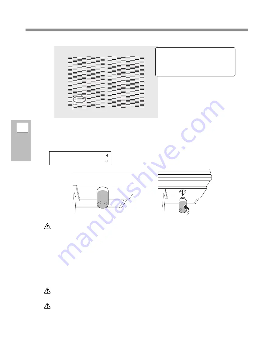
Check  f or the group  with dot drop -out by  viewing the p rinting-test results.

D o t   d r o p -o u t

I  the  rinting test results are di cult 

to interp ret

Examine the results from different angles 

in a well-lit location. Take advantage of 

reflected light to enable visual checking.

P ress [ ENTER] .

W

hen the screen shown below ap p ears,  remove the drain bottle and discard the dis-

charged fluid

EMPTY


CAUTIO N 

B ef ore y ou detach the drain bottle,  be sure to wait f or the screen to disp lay  


I  

  ter discarding the discharged fluid,  rom tl  

attach the drain bottle to the machine.

ai ing to fo o  this procedure  a  cause discharged  uid to  o  out of the 

achine and spi  soi ing  our hands or the  oor

Q uick ly  attach the emp tied drain bottle to the machine once more.

P ress [ ENTER] .

W ARNING  

e er  lace discharged fluid or ink near an o en flame

oing so  a  cause a fire

CAUTIO N 

o store discharged fluid tem oraril ,  lace it in the included drain bottle 

or in a durable sealed container such as a metal can or p oly ethy lene tank ,  
and cap  the container tightly .

n  spi age or  apor  ea age  a  cause a fire  an odor  or ph sica  distress

is ose o  discharged fluid  ro erl , in accordance  ith the la s in e ect in  our locale

Discharged fluid is flammable and contains toxic ingredients. Never attempt to incinerate discharged fluid 

Summary of Contents for TrueVIS SG-300

Page 1: ...rors please inform Roland DG Corp Roland DG Corp assumes no responsibility for any direct or indirect loss or damage that may occur through use of this product regardless of any failure to perform on...

Page 2: ...ITY OF SUCH DAMAGE For the USA and Canada FCC CAUTION Changes or modifications not expressly approved by the party responsible for compliance could void the user s authority to operate the equipment T...

Page 3: ...Adjustment Correcting for Misalignment in Bidirectional Printing 37 Step 3 Batch Settings 39 Step 4 Setting the Base Point 52 Step 5 Printing Tests and Normal Cleaning 53 Step 6 Starting Output 55 B a...

Page 4: ...e se t s 112 Saving the Current Settings Preset Saving 112 Loading a Saved Preset 114 S e t t i n g s f o r t h e M e d i a H e a t i n g S yst e m 115 What Is the Media Heating System 115 Making the...

Page 5: ...inistrator Menu 1 5 3 O u t p u t O p e r a t i o n M a n a g e m e n t 15 4 Printing a System Report 154 Determining What Happens When Ink Runs Out 154 Displaying the Amount of Media Remaining 155 Ma...

Page 6: ...ing 193 A b o u t t h e B l a d e 19 4 L o ca t i o n s o f t h e P o w e r Ra t i n g a n d S e r i a l N u m b e r L a b e l s 19 5 Specifications 19 6 Copyright 2016RolandDGCorporation http www rol...

Page 7: ...n i t 6 O p e r a t i o n P a n e l 11 W a r n i n g L a b e l s 12 V i g n e t t e s d a ve r t i sse m e n t 13 M e n u L i st 14 M a i n M e n u 14 F u n ct i o n M e n u 18 L a n g u a g e a n d U...

Page 8: ...ch as when load ing media In all other situations keep the front cover closed 3 Loading lever f ront Operate this when you load media 4 P anel cover op eration p anel Open this cover to access the ope...

Page 9: ...e this to connect the power cable 3 Loading lever rear Operate this when you load media 4 Media holders Use these when you load media 5 Shaf ts Use these when you load media Side No Name Function over...

Page 10: ...When loading media be sure to place the pinch rollers within the ranges indicated by these patterns 4 P inch rollers lef t p inch roller right p inch roller and middle p inch roller These clamp the m...

Page 11: ...hthemediapasses Asuc tion fan that keeps the media from coming loose and a print heater that helps fix the ink are built in 9 Ap ron Thishasabuilt indryertospeedupdryingoftheink 0 W ip er Cleansthepri...

Page 12: ...message prompting you to close the cover will be displayed on the screen Follow the instruction shown on the screen and close the cover After you close the cover the following message appears on the s...

Page 13: ...N C TI O N ke y Press this when entering the setting menu for cleaning of the print heads printing tests and so on FUNCTION P AUSE P A U S E ke y This pauses the printing operation It lights when ope...

Page 14: ...e a l t h W h e n p e r f o r m i n g aintenance or for e a p e hen disposing of dis charged uid ear protecti e e e ear and protecti e g l o ve s r e f e r t o t h e sa f e t y d a t a sh e e t S D S...

Page 15: ...t e ct i o n o cu l a i r e e t d e s g a n t s p r o t e c teurs se reporter a fiche signa ti ue S Attention Risq ue de p incement F a i r e a t t e n t i o n d e n e p a s co i n ce r l e s d o i g...

Page 16: ...S T P RI N T m e n u To t h e TE S T P RI N T m e n u To t h e N A M E 8 m e n u To t h e N A M E 1 m e n u MENU MENU MENU MENU NAME1 NAME8 NAME1 NAME8 1 NAME8 MENU C o n t i n u e To t h e S E TTI N...

Page 17: ...5 To t h e N O N E m e n u To t h e S U P E R C L m e n u To t h e E M P TY M O D E m e n u To t h e TE S T P RI N T P O S m e n u To t h e I N TE RV A L TI M E m e n u C o n t i n u e C o n t i n u e...

Page 18: ...i n u e C o n t i n u e C o n t i n u e C o n t i n u e To t h e D RA I N B O TTL E m e n u To t h e M A C A D D RE S S m e n u To t h e RE P L A C E W I P E R m e n u To t h e S H E E T TY P E m e n...

Page 19: ...h e TE S T P RI N T 2 m e n u To t h e A U TO D I S P L A Y m e n u To t h e TE S T P RI N T 2 m e n u To t h e TE S T P RI N T m e n u To t h e S C A N S E TTI N G m e n u To t h e TE S T P RI N T m...

Page 20: ...t h e B A S E P O I N T m e n u To t h e P RI N T m e n u To t h e P RI N T C U T A D J m e n u To t h e D RY E R m e n u P r e s s To t h e P RI N T L I G H T m e n u 1 This is displayed when the wid...

Page 21: ...List 1 Machine H ighlights 19 Language and Unit Menu C F MENU LANGUAGE JAPANESE MENU LANGUAGE ENGLISH LENGTH UNIT mm INCH TEMP UNIT C F W h i l e h o l d i n g d o w n s w i t c h o n t h e s u b p o...

Page 22: ...i o n Install the machine in a location having the specified temperature and relative humidity Install the machine in a quiet stable location offering good operating conditions T h e p r i n t h e a d...

Page 23: ...e it forcefully The impact may rupture the internal pouches and cause the ink to leak Never attempt to disassemble the machine Never attempt to refill the ink If ink gets on your hands or clothing was...

Page 24: ...22...

Page 25: ...u t p u t 5 5 B a si c S e t t i n g s f o r C u t t i n g 5 7 H i n t s a n d Ti p s f o r C u t t i n g S e t t i n g s 5 7 I m p o r t a n t N o t e o n C u t t i n g 5 7 P r e ve n t i n g P u l l...

Page 26: ...witch of f the sub p ower Th e co n t i n u e d a p p l i ca t i o n o f h e a t a t a si n g l e l o ca t i o n m a y ca u se t h e r e l e a se of to ic gases fro the edia or pose a fire ha ard P ro...

Page 27: ...u e d a p p l i ca t i o n o f h e a t a t a si n g l e l o ca t i o n m a y ca u se t h e r e l e a se of to ic gases fro the edia or pose a fire ha ard P rocedure A itch o the sub o er hene er rint...

Page 28: ...Be sure to first switch off the sub power If the main power is accidentally switched off immediately turn the main and sub power back on Sleep Mode P ower saving Feature This machine is provided with...

Page 29: ...s on the material of the media Max imum media thick ness including back ing p ap er a When performing printing only 1 0 mm 39 mil When performing cutting 0 4 mm 15 mil Roll outer diameter 210 mm 8 2 i...

Page 30: ...output as a batch Step 4 Setting the B ase P oint P 5 2 Set the base point in order to determine the output area Step 5 P rinting Tests and Normal Cleaning P 5 3 Before you carry out actual printing...

Page 31: ...g 5 5 lb 3 0 inch model Th e m a ch i n e m a y f a i l t o w i t h st a n d t h e w e i g h t a n d t i p o ve r o r ca u s e t h e m e d i a t o f a l l 1 Install the media on the media holders Not...

Page 32: ...r t a n t P o s i t i o n t h e L m e d i a h o l d e r c o r r e c t l y If the position of the L media holder is incorrect media may not be fed properly which will have an adverse effect on the prin...

Page 33: ...lef t edge Ensure that the edge of the media is not within the range of 2 0 mm 0 7 9 in to the right of the grit p attern of the lef t edge or 2 0 mm 0 7 9 in to the lef t of other grit p atterns L e...

Page 34: ...lders by tightening the retaining screws R L 3 P ull out the media over the p laten A Mak e sure the f ront cover is op en B P ass the leading edge of the media between the p inch rollers and the grit...

Page 35: ...ace At this time the message CLOSE FRONT COVER is displayed on the screen but continue operations without closing the front cover D Move to the f ront of the p rinter G ently hold down the media and r...

Page 36: ...l l e r s affi ed ith b l u e st i cke r s Ri g h t p i n ch r o l l ers affi ed ith b l u e st i cke r s G r i t p a t t e r n a b o u t 10 m m 0 3 9 i n a b o u t 10 m m 0 3 9 i n G r i t p a t t e...

Page 37: ...he remaining middle pinch rollers Attaching and detaching middle p inch rollers A t t a ch i n g d e t a ch i n g l o ca t i o n To attach I n se t a l l t h e w a y a n d sl i d e a l o n g t h e r a...

Page 38: ...cover is closed the print head carriage moves and detects the width of media This operation is called initialization When initialization ends SETUP on the operation panel lights and the printable widt...

Page 39: ...rformed in the following cases When using this machine for the first time When changing the media to use When printing is not improved by performing simple correction for bidirectional printing P 120...

Page 40: ...llowing figure select 5 for H1 4 for H2 When you cannot choose between two sequential numbers select a value that is between them you can set correction values in units of 0 5 D Set the correction val...

Page 41: ...ecessary items as a batch You can save the setting details as a preset Note that you can set all the items set here individually as well 1 Start the MEDIA SETTING menu A Load the media Check that the...

Page 42: ...disp lay ed op en the f ront cover D Move the height adj ustment lever to adj ust the p rint head height When you change the position of the height adjustment lever the display screen will change When...

Page 43: ...to select SET CALIBRATION B ress to con rm our entr The test pattern of feed correction is printed You can select NEXT and press ENTER to proceed to the next menu C P ress ENTER INPUT D V iew the p r...

Page 44: ...ress to con rm our entr 5 P erf orm the correction f or misalignment in bidirectional p rinting Sep arate setting P 12 0 A P ress to select SET B ress to con rm our entr The test pattern of bidirectio...

Page 45: ...t need to change the correction value press ENTER again I P ress to select DO NE J ress to con rm our entr 6 Decide to p erf orm the setting f or cutting or not A P ress or to select NEX T or SET Sele...

Page 46: ...back ing p ap er is also cut P ress to select Y ES Two shap es are p eeled of f sep arately P ress to select DO NE E ress to con rm our entr If you select YES proceed to the next procedure If you sele...

Page 47: ...may occur due to the thickness of the media or the head height We recommend that you make corrections to match the media you are using A P ress to select SET B ress to con rm our entr The test patter...

Page 48: ...condition The point where the cutting line intersects the correction value scale is the correction value Check the scan direction the direction of print head movement and the feed direction the media...

Page 49: ...m the setting again If you select DONE proceed to the next procedure 9 Correct the misalignment of the p rinting and cutting p ositions when using crop mark s Sep arate setting P 144 MEMO When you rem...

Page 50: ...ition are aligned P ress to select DO NE E ress to con rm our entr If you select YES the test pattern C C2 for setting the correction values is printed and cut Pro ceed to the next procedure If you se...

Page 51: ...ES Cutting p osition and p rinting p osition are aligned P ress to select DO NE J ress to con rm our entr If you select YES the test pattern C C1 is printed and cut again Go back to step Gand perform...

Page 52: ...vinyl chloride media Setting time About three minutes D ress to con rm our entr 11 Save the settings as a p reset A P ress to select SAV E PRESET B ress to con rm our entr If you select NEXT and pres...

Page 53: ...ED This completes the operation of the MEDIA SETTING menu Canceling B atch Settings bef ore They Are Comp leted P rocedure A P ress MENU during setup B P ress to select Y ES C ress to con rm our entr...

Page 54: ...r i a g e m o ve m e n t d i r e ct i o n B a se p o i n t r i g h t e d g e o f t h e o u t p u t a r e a O u t p u t a r e a M e d i a f e e d d i r e ct i o n MEMO Note that the left and right pos...

Page 55: ...Whenperformingprintingtestssuccessively youcanselect SCAN verticalprinting or FEED horizontal printing as the print position for the 2nd and later tests in comparison to the 1st test P Perfor ing Prin...

Page 56: ...tarts The approximate remaining time for the procedure is displayed on the screen The display shown below is an example 01 45 1 minute and 45 seconds CLEANING 01 45 When finished the screen shown belo...

Page 57: ...e Ethernet connector located on the side of the printer lights up in green A ct i vi t y L E D Thisflashesinyellowwhiledatais being received from the network S t a t u s L E D This indicates the statu...

Page 58: ...ht is open Never open a cover front left or right while output is in progress Doing so interrupts printing Data from the computer is not accepted when SETUP is dark Printing does not start until HEATE...

Page 59: ...u a r e p e r f o r m i n g c u t t i n g o n l y d o n o t u s e t h e m e d i a c l a m p s When you are performing cutting only remove the media clamps or move them to locations where they do not c...

Page 60: ...w PREFEED E P ress or to select ENAB LE PREFEED F ress to con rm our entr G P ress MENU to go back to the original screen Descrip tion This feeds out media according to the size of the data sent from...

Page 61: ...arry out the cutting test A Close the f ront cover B P ress or to move the cutting carriage to the location where y ou want to carry out the cutting test You can freely set the location for the cuttin...

Page 62: ...step to set the blade force D P ress or to select a value Two shap es are p eeled of f together Raise the blade force B ack ing p ap er is also cut Reduce the blade force E ress to con rm our entr F...

Page 63: ...ith crop marks you can make it possible to align the positions using the crop marks when you load the media again to cut it In this manual this printing method is referred to as printing and cutting w...

Page 64: ...r o p m a r k 1 5 m m a b o u t 0 06 i n A r e a w h e r e o u t p u t i s p o ssi b l e W h e r e t o cu t t h e m e d i a o f f 9 0 m m o r m o r e 3 5 i n o r m o r e 2 2 5 m m 0 89 i n P i n ch r...

Page 65: ...s aligned with the printing position For information on how to make the setting refer to the documentation for the software RIP you re using B Load the media that y ou removed in step 2 in the machine...

Page 66: ...ou W ant to Stop Crop Mark Detection bef ore It Is Finished and Start Cutting P rocedure A P ress P AUSE during detection of crop mark s The screen shown below appears and crop mark detection stops D...

Page 67: ...creen indicate which color has run out as shown below 1 2 3 4 f an in pouch runs out the nu er of the co or that has run out i ash O ut of TR cleaning liq uid W arnings IftheTRcleaningliquidrunsout th...

Page 68: ...so a ead to a fire ccidenta ingestion chi dren a pose a hea th ha ard P recautions regarding Ink P ouch Rep lacement Be sure to replace each pouch with an item of identical type and color Never use an...

Page 69: ...h During storage the ink components may have precipitated When replacing an ink pouch gently shake the new ink pouch to mix its contents before setting the ink pouch in the tray E Set the new ink p ou...

Page 70: ...ear each or an other such o idi ing agent or e p osi e ateria A n y l o ca t i o n w i t h i n t h e r e a ch o f ch i l d r e n oing so a ead to a fire ccidenta ingestion chi dren a pose a hea th ha...

Page 71: ...ation 6 9 C Remove the TR cleaning liq uid p ouch f rom the tray D Set the new TR cleaning liq uid p ouch in the tray C h e ck t h a t t h e h o o k h a s ca u g h t H o o k E Set the p ouch tray in t...

Page 72: ...e finished loading the media SETUP lights This work is referred to as Setup of Media 1 P ull out the media over the p laten A O p en the f ront cover B Move the media clamp s to the lef t and right en...

Page 73: ...llers and the grit rollers P i n ch r o l l e r G r i t r o l l e r M e d i a F r o n t E Mak e sure the f ront cover is op en F Lower the loading lever rear The media is held in place At this time th...

Page 74: ...le t and right inch rollers a xed ith blue stickers on both edges o the media Place the pinch rollers within the ranges indicated by grit patterns Position them approximately 10 mm 0 39 in from each e...

Page 75: ...r there are grit rollers Be sure to remove the remaining middle pinch rollers G r i t p a t t e r n P 3 5 A t t a ch i n g a n d d e t a ch i n g m i d d l e p i n ch r o l l e r s M i d d l e p i n c...

Page 76: ...When initialization ends SETUP on the operation panel lights and the printable width is displayed on the screen This completes the setup of the media P ausing or Canceling O utp ut You can pause and c...

Page 77: ...r Th e m e d i a i s f e d t o t h e f r o n t Th e m e d i a i s cu t o f f h e r e B l a d e p r o t e ct o r P r i n t e d p o r t i o n You can configure settings in the software RIP for automati...

Page 78: ...the software RIP if the media clamps are attached the machine will detect them and interrupt the operation When performing cutoff do not use to pull the media back Unless the end of the media has been...

Page 79: ...A r e U n e ve n 9 2 M i xi n g t h e I n k b y S h a ki n g t h e P o u ch Tr a y 9 2 I f C o l o r s A r e S t i l l U n e ve n 9 2 W h e n D o t D r o p o u t s U n e ve n C o l o r s A r e N o t...

Page 80: ...arly prone to the buildup of grime Clean by wiping with a cloth moistened with neutral detergent diluted with water then wrung dry Imp ortant This machine is a precision device and is sensitive to dus...

Page 81: ...d to o out of the tu e and spi soi ing our hands or the oor B Q uick ly attach the emp tied drain bottle to the machine once more C P ress ENTER D P ress to select Y ES E P ress ENTER The display retu...

Page 82: ...ay the screen shown below SUB MENU MAINTENANCE D P ress once and then p ress several times to disp lay the screen shown below MAINTENANCE E P ress ENTER F W hen the screen shown below ap p ears remove...

Page 83: ...nk affixes to the inside of the drain bottle which makes it difficult to check the amount of dis charged fluid In this situation clean the inside of the drain bottle by using one of the following proc...

Page 84: ...ng p owerf ul cleaning Perform medium cleaning or powerful cleaning when problems such as dot drop out are not corrected after performing normal cleaning P 83 W h e n N o r m a l C l e a n i n g I s N...

Page 85: ...rful cleaning P rocedure A P erf orm a p rinting test P 5 3 S t e p 5 P r i n t i n g Te st s a n d N o r m a l C l e a n i n g When the printing test is finished the screen shown below appears Remove...

Page 86: ...MEDIUM CL CLEANING POWERFUL CL F P ress FUNCTIO N to go back to the original screen G P erf orm a p rinting test again to mak e sure the dot drop out has been corrected P 5 3 S t e p 5 P r i n t i n...

Page 87: ...ing liquid used for manual cleaning contact your authorized Roland DG Corp dealer The print heads are components that wear out Periodic replacement is required with the frequency of replacement depend...

Page 88: ...ginning CAUTIO N e sure to er orm o erations as s eci ed b the instructions and ne er touch an area not s eci ed in the instructions S u d d e n m o ve m e n t o f t h e m a ch i n e m a y ca u se i n...

Page 89: ...cut rail G P ress ENTER H W hen the f ollowing screen is disp lay ed close the lef t cover When the left cover is closed the print head carriage moves Click I W hen the f ollowing screen is disp lay e...

Page 90: ...een is displayed 2 Clean the wip er and the area around the p rint heads A ouch the location sho n in the gure to discharge an static electricit B Moisten the cleaning stick with the cleaning liq uid...

Page 91: ...ollo ing gure Be especially careful to clean away any fibrous dust lint A r e a t o cl e a n D u r i n g t h i s w o r k b e ca r e f u l n o t t o t o u ch t h e p r i n t h e a d su r f a ce n o zz...

Page 92: ...hed ress B W hen the f ollowing screen is disp lay ed close the right cover Click C W hen the f ollowing screen is disp lay ed close the lef t cover Click D W hen the f ollowing screen is disp lay ed...

Page 93: ...e is displayed on the screen The display shown below is an example 01 45 1 minute and 45 seconds CLEANING 01 45 When cleaning finishes the screen shown below appears again CLEANING MANUAL CL H P ress...

Page 94: ...ay Removing the ink pouches may lead to the ink leaking Before shaking an ink pouch wipe off any ink from around the mouth of the ink pouch If you do not wipe off the ink it may splatter when you shak...

Page 95: ...n dotdrop outcannotbecorrectedevenafterperformingcleaningusingtheothercleaningfunctions normal medium powerful and manual cleaning P 7 8 D a i l y M a i n t e n a n ce P 83 W h e n N o r m a l C l e a...

Page 96: ...ed fluid rom tl attach the drain bottle to the machine ai ing to fo o this procedure a cause discharged uid to o out of the achine and spi soi ing our hands or the oor I Q uick ly attach the emp tied...

Page 97: ...ure appears and then cleaning starts The approximate re maining time for the procedure is displayed on the screen The display shown below is an example 01 45 1 minute and 45 seconds CLEANING 01 45 Whe...

Page 98: ...nd cautiously Note that this operation is an emergency measure Depending on symptoms it may damage normal areas and cause symptoms to worsen If you have any questions contact your authorized Roland DG...

Page 99: ...ci ed b the instructions and ne er touch an area not s eci ed in the instructions S u d d e n m o ve m e n t o f t h e m a ch i n e m a y ca u se i n j u r y Required items Wiper Tweezers 1 Enter the...

Page 100: ...ge moves to a location where wiper replacement is possible and then the screen shown below appears 2 Rep lace the wip er A O p en the right cover Preparation is complete once the following screen is d...

Page 101: ...the wiper makes the removal easier H o o k P l a ce t h e i n cl i n e d e n d o n t h e b a ck si d e If the wiper is placed inversely the proper cleaning becomes impossible A t t a ch t h e h o o k...

Page 102: ...lean the wiper tray Clean the wiper tray and then replace the tray pads CAUTIO N e sure to er orm o erations as s eci ed b the instructions and ne er touch an area not s eci ed in the instructions S u...

Page 103: ...or the oor W ARNING e er lace discharged fluid or ink near an o en flame oing so a cause a fire CAUTIO N o store discharged fluid tem oraril lace it in the included drain bottle or in a durable seale...

Page 104: ...sp lay ed op en the right cover B W hen the f ollowing screen is disp lay ed op en the waste valve W a st e va l ve C W hen the f ollowing screen is disp lay ed close the right cover D W hen the f oll...

Page 105: ...ne is filled with TR cleaning liquid The ap proximate remaining time for the procedure is displayed on the screen The display shown below is an example 01 40 1 minute and 40 seconds 01 40 CLEANING 01...

Page 106: ...a y ca u se i n j u r y CAUTIO N Never touch the tip of the k nif e D o i n g so m a y r e su l t i n i n j u r y Required items Blade for replace 1 Enter the REP LACE K NIFE menu A Remove any media...

Page 107: ...is disp lay ed op en the f ront cover Preparation is complete once the following screen is displayed 2 Rep lace the blade A Remove the blade holder B Rep lace the blade 1 P ress the p in to p ush out...

Page 108: ...LACE K NIFE menu A Close the f ront cover B P ress ENTER When the following screen is displayed again the blade replacement is finished MAINTENANCE REPLACE KNIFE C P ress MENU to go back to the origin...

Page 109: ...O N Never touch the tip of the k nif e D o i n g so m a y r e su l t i n i n j u r y Required item Replacement blade for separating knife 1 Enter the REP LACE K NIFE menu A Remove any media B P ress M...

Page 110: ...p lace the sep arating k nif e A Remove the sep arating k nif e 1 Loosen the screw until it slip s out 2 G rasp the screw p ortion and then slowly p ull it out in the direction of the arrow When doing...

Page 111: ...that the knife does not slip out of position at this time 3 Ex it the blade rep lacement menu A Close the f ront cover B P ress ENTER When the following screen is displayed again the blade replacemen...

Page 112: ...ve humidity of 20 to 80 with no condensation Temperatures that are too high may degrade the ink and cause malfunc tion Temperatures that are too low may cause the ink to freeze and damage the print he...

Page 113: ...i cky M e d i a 13 0 A d va n ce d C u t t i n g S e t t i n g s 13 1 F i n e t u n i n g t h e C u t t i n g C o n d i t i o n s 13 1 A ccu r a t e l y A d j u st i n g t h e C u t t i n g i n A m o...

Page 114: ...ss to con rm our entr The current menu settings are saved and then the screen shown below appears S F Set the p reset name 1 P ress or to select a character 2 W hen y ou have selected the character y...

Page 115: ...h e D r yi n g Ti m e a f t e r P r i n t i n g ADJUST BI DIR SIMPLE SETTING P 12 0 C o r r e ct i n g f o r M i sa l i g n m e n t i n B i d i r e ct i o n a l P r i n t i n g ADJUST BI DIR DETAIL SE...

Page 116: ...AD NAME1 D Select the p reset that y ou want to load 1 P ress or to select the name of the p reset y ou want to load 2 ress to con rm our entr E P ress MENU to go back to the original screen Descrip t...

Page 117: ...NG Never use media that cannot withstand the heat oing so a resu t in fire or the re ease of to ic gases or a degrade the m e d i a W ARNING Never use the p laten or dry er f or any p urp ose f or whi...

Page 118: ...wrinkle DRY ER G eneral G uide f or Setting the Temp erature DRYER 0 When ink drying is poor raise the temperature Note however that a temperature that is too high may degrade the media or cause it to...

Page 119: ...rature try reducing the amount of ink O ther p oints to remember When recommended settings for temperature print mode and other values are given as the use condition of your media use the suggested se...

Page 120: ...on ENAB LE M e d i a f e e d i s p e r f o r m e d u n t i l t h e t r a i l i n g e d g e o f t h e p r i n t i n g a r e a i s p o si t i o n e d o n t h e d r ye r Th e m a r g i n b e t w e e n t...

Page 121: ...lay the screen shown below E P ress or to select the dry ing time F ress to con rm our entr G P ress MENU to go back to the original screen Descrip tion Set the drying time after the 1st page is prin...

Page 122: ...ttern f or bidirectional p rinting A P ress MENU B P ress several times to disp lay the screen shown below MENU C P ress to disp lay the screen shown below D P ress ENTER A test pattern is printed 2 S...

Page 123: ...W hen y ou have successf ully p erf ormed the correction p ress MENU to go back to the original screen Descrip tion Thismachineperformsbidirectionalprinting inwhichtheheadsperformprintingduringboththe...

Page 124: ...hat the media is not sagging B P ress MENU C P ress several times to disp lay the screen shown below MENU CALIBRATION D P ress to disp lay the screen shown below CALIBRATION E P ress ENTER A test patt...

Page 125: ...Ifthegapandoverlaparesmallerforanotherfigure setthecorrectionvalueagain G W hen y ou have successf ully p erf ormed the correction p ress MENU to go back to the original screen Descrip tion Themovemen...

Page 126: ...on of the height adjustment lever the display screen will change When the lever is moved to the High direction the buzzer sounds twice When it is moved to the Low direction the buzzer sounds once H e...

Page 127: ...ransp arent Media P rocedure A P ress MENU B P ress several times to disp lay the screen shown below MENU SUB MENU C P ress to disp lay the screen shown below D P ress to disp lay the screen shown bel...

Page 128: ...E P ress or to select a value Larger values cause the media to move more slowly enabling you to extend the drying time ac cordingly F ress to con rm our entr G P ress MENU to go back to the original...

Page 129: ...ndcannotmovesmoothly decreasingthisvalue reducing the suction force may correct the problem AUTO The suction force is automatically adjusted to the optimal level for the media width F ress to con rm o...

Page 130: ...F OFF matches the range of print head movement to the printing data Movement is limited to the minimum amount necessary and this can be expected to yield the fastest output Note however that because t...

Page 131: ...hed during printing automatic cleaning is performed before the next printing operation starts Becauseprintingisnotpaused unevencolorissuesduetopausedoperation do not occur INTERV AL TIME Automaticclea...

Page 132: ...entr G P ress MENU to go back to the original screen Descrip tion Some types of media may tend to stick to the platen Starting printing with the media sticking to the platen may make normal media feed...

Page 133: ...of f the circle The square also peels off Increase the value of FORCE Some uncut areas remain Decrease the value of SPEED P eel of f the sq uare The blade leaves faint traces on the backing paper Do...

Page 134: ...ring cutting the speed at which the blade travels when it moves to the next cutting line after cutting one cutting line If the media comes loose during no load feed and the blade damages the surface o...

Page 135: ...touch and may soil and damage the printed surface It is important to be especially careful about this when you are using media that has poor ink adhesion properties A m o u n t o f b l a d e e xt e n...

Page 136: ...hen p ress twice to disp lay the screen shown below CALIBRATION E P ress twice to disp lay the screen shown below FEED SETTING 0 00 0 00 F P ress or to select the correction value Set the correction v...

Page 137: ...ting and Cutting P ositions 1 P erf orm the p rep arations bef ore the correction A Mak e sure the AUTO ENV MATCH menu item is set to ENAB LE P 13 9 V i e w i n g t h e A u t o m a t i c E n vi r o n...

Page 138: ...ting position are not aligned proceed to the next procedure 3 Set the correction values A P ress twice to disp lay the screen shown below B P ress ENTER The test pattern P C2 is printed and cut C P re...

Page 139: ...e the adjustment Descrip tion Performthisadjustmentwhenprintingfollowedimmediatelybycuttingyieldspositioningforprintingandcutting that is slightly misaligned Print alignment marks perform detection of...

Page 140: ...o back to the original screen Descrip tion You can also make the settings for the cutting conditions in the software RIP By default the settings made with the software RIP take priority To make the cu...

Page 141: ...t reduces misalignment in the scanning direction the direction of cutting carriage movement during printing and cutting Normally set this item to ENABLE P rocedure A P ress MENU B P ress to disp lay t...

Page 142: ...veral times to disp lay the screen shown below FUNCTION D P ress once and then p ress several times to disp lay the screen shown below E P ress F Determine the correction values P r i n t i n g p o si...

Page 143: ...r one second or longer cancels the cutting operation P 7 4 P a u si n g o r C a n ce l i n g O u t p u t Descrip tion With this machine you can pause a cutting operation to correct the misalignment of...

Page 144: ...the location of the base point as shown in the following figure You cannot set the align points unless you specify the base point Redoing the setting for the base point clears any align points that h...

Page 145: ...n t 1 B P ress FUNCTIO N to disp lay the screen shown below FUNCTION C P ress to disp lay the screen shown below D P ress ENTER The ALIGN POINT is set The characters B1 are displayed on the screen W1...

Page 146: ...the screen shown below MENU C P ress then to disp lay the screen shown below D P ress to disp lay the screen shown below E P ress ENTER The test pattern C C1 is printed and cut The test pattern is pr...

Page 147: ...ue Check the scan direction the direction of print head movement and the feed direction the media feed direction C u t t i n g l i n e I n t h i s ca se t h e co r r e ct i o n va l u e i s 0 3 C u t...

Page 148: ...If further adjustment is needed press then to go back to step Fand fine tune the adjustment Descrip tion Depending on the composition of the media the positioning of printing and cutting may be misal...

Page 149: ...Tak e Up Sy stem About Media Tak e Up Sy stem The media take up system hereinafter called take up system is optional part For information on how to assemble install and operate the take up system refe...

Page 150: ...r o i d d e vi ce s e ve n i f t h e i r o p e r a t i n g syst e m i s ve r si o n 4 4 o r l a t e r Supported languages Ja p a n e se E n g l i sh Communication method B l u e t o o t h 4 0 L E Th...

Page 151: ...to one printer from a mobile terminal on which Mobile Panel has been installed You can register multiple printers on Mobile Panel but you cannot connect to multiple printers at the same time N o p a i...

Page 152: ...o o t h C o m m u n i ca t i o n Using Bluetooth communication in the vicinity of TVs or radios may lead to noise in the image or audio Roland DG Corp accepts no responsibility for the leakage of info...

Page 153: ...hown below E P ress or to select FEED F ress to con rm our entr G P ress MENU to go back to the original screen Descrip tion When performing printing tests successively you can select SCAN vertical pr...

Page 154: ...aper tubes cores with an internal diameter of 2 inches are optional items For information about purchasing them contact your authorized Roland DG Corp dealer Media ange for inch edia I n se r t t h e...

Page 155: ...r i n t i n g t h e A m o u n t o f Re m a i n i n g M e d i a 15 8 S yst e m M a n a g e m e n t o f P r i n t e r 15 9 S e t t i n g t h e M e n u L a n g u a g e a n d t h e U n i t s o f M e a su...

Page 156: ...he screen shown below D P ress ENTER The printing of the system report starts E P ress MENU to go back to the original screen Determining W hat H ap p ens W hen Ink Runs O ut This lets you change acco...

Page 157: ...before you begin printing When CONT is selected color unevenness can be avoided however printing does not stop even if ink runs out completely To replace an ink pouch wait until printing ends or pres...

Page 158: ...by removing the media or raising the loading lever the amount remaining at that time flashes on the screen Because the amount of media remaining is not updated auto matically when you change the media...

Page 159: ...the screen shown below E P ress or to select ENAB LE F ress to con rm our entr If you select ENABLE you must set the EDGE DETECTION menu item to DISABLE P 12 5 U si n g Tr a n sp a r e n t M e d i a...

Page 160: ...iginal screen Descrip tion Use this when you want to make a record of the remaining length of the media currently in use Printing the amount of media remaining before you change the media enables you...

Page 161: ...AGE ENGLISH C ress to con rm our entr D P ress or to select the measurement unit f or length E ress to con rm our entr F P ress or to select the measurement unit f or temp erature G ress to con rm our...

Page 162: ...nication to ENABLE However when you are operating this machine from its operation panel you cannot perform operations from Mobile Panel P 164 P r o ce d u r e f r o m P r e p a r i n g t o M o ve t o...

Page 163: ...p Mode P ower saving Feature P rocedure A P ress MENU B P ress several times to disp lay the screen shown below MENU SUB MENU C P ress once and then p ress several times to disp lay the screen shown b...

Page 164: ...INK Ink ty p e FIRMW ARE Firmware version NETW O RK Network settings such as the IP address B LUETO O TH B luetooth communication state To B L U E TO O TH To M O D E L To I P A D D RE S S To M A C A D...

Page 165: ...factory default values However the settings for MENU LANGUAGE LENGTH UNIT and TEMP UNIT are not returned to their factory default values P rocedure A P ress MENU B P ress several times to disp lay the...

Page 166: ...it may result in problems such as clogging of the print heads When moving the machine keep it at a temperature between 5 to 40 C 41 to 104 F and at relative humidity between 20 to 80 with no condensa...

Page 167: ...nce the following screen is displayed H Remove the blade holder 2 Enter the menu f or discharging the wip er tray cleaning liq uid A P ress MENU B P ress several times to disp lay the screen shown bel...

Page 168: ...ing so a cause a fire CAUTIO N o store discharged fluid tem oraril lace it in the included drain bottle or in a durable sealed container such as a metal can or p oly ethy lene tank and cap the contain...

Page 169: ...en the right cover B W hen the f ollowing screen is disp lay ed op en the waste valve W a st e va l ve C W hen the f ollowing screen is disp lay ed close the right cover D W hen the f ollowing screen...

Page 170: ...lame oing so a cause a fire CAUTIO N o store discharged fluid tem oraril lace it in the included drain bottle or in a durable sealed container such as a metal can or p oly ethy lene tank and cap the c...

Page 171: ...relocation without taking too much time and turn on the main power of the machine immediately after it is transferred To install the machine again follow the procedure in the Setup Guide D Switch on...

Page 172: ...17 0...

Page 173: ...W r i n kl e s o r S h r i n ks 17 7 M e d i a F e e d I s N o t S t r a i g h t 17 8 M e d i a F e e d I s N o t S m o o t h 17 8 P r i n t H e a d s S t o p M o vi n g 17 9 W h a t t o D o F i r st...

Page 174: ...arryoutcorrection Theoptimaladjustment value may vary depending mainly on the thickness of the media Set or select an adjustment value that is suited to the media When further correction is required s...

Page 175: ...e p 3 B a t ch S e t t i n g s P 112 U si n g P r e se t s The Media B ecomes Soiled W hen P rinted Do the p rint heads contact the media The height of the print heads may be too low Also if the medi...

Page 176: ...a level and stable location Never install the machine in a location where it is tilted or where it may wobble or experience vibration Also make sure that the printheadsarenotexposedtomovingair Thesef...

Page 177: ...ou using media that ex hibits large ex p ansion and contraction When you are performing printing followed immediately by cutting misalignmentoccursifthemediaexpandsorcontracts If this happens try perf...

Page 178: ...grit rollers dirty Check to make sure the grit rollers are free of buildup of foreign material such as media scraps P 7 8 C l e a n i n g Are the media clamp s at tached When you are performing print...

Page 179: ...nt heater has warmed up causes the temperature of the media to rise suddenly which may cause the media to shrink or wrinkle during printing Before loading media switch off the sub power and allow the...

Page 180: ...ect coming into contact with the media or the shaf ts Make sure the media and the shafts do not touch anything else Thismayaffectoutput evenwhenthefeedappearstobesmooth P 2 9 S t e p 1 L o a d i n g R...

Page 181: ...movetothehomeposition insidethecoverR itmeanstheoperationhasendedsuccessfully If the P rint H eads Still Do Not Move Try switching off the main power then again switching on the main power followed by...

Page 182: ...lace where the audible click is heard locks the print head carriage in place Click D G ently ap p ly p ressure f rom the right side to mak e sure the p rint head carriage does not move to the lef t If...

Page 183: ...the cables securely S e t u p G u i d e Is the network routing ap p rop riate Checkwhetherthenetworkroutingisappropriate Tryconnecting the computer and the machine to the same hub or connecting them...

Page 184: ...output resumes when the data is resent P 66 I n k P o u ch Re p l a ce m e n t P 15 4 D e t e r m i n i n g W h a t H a p p e n s W h e n I n k Ru n s O u t The Media H eating Sy stem Doesn t W arm U...

Page 185: ...bile Panel has been installed You can register multiple printers on Mobile Panel but you cannot connect to multiple printersatthesametime Ifyouwanttooperatemultipleprinters use Mobile Panel to select...

Page 186: ...obstacles between the printer and the mobile terminal Is the mobile terminal s B lue tooth connection turned on Check the status of the Bluetooth connection of the mobile ter minal on which Mobile Pa...

Page 187: ...n the operation panel to clear the message Load new media E M P TY D RA I N B O TTL E This appears when a certain amount of discharged fluid collects in the drain bottle Discard the discharged fluid i...

Page 188: ...mpty Replaceitwith a new TR cleaning liquid pouch P 68 TR C l e a n i n g L i q u i d P o u ch Re p l a ce m e n t W I P E R TRA Y I S N O T F I L L E D The wiper tray was not full with TRcleaningliqu...

Page 189: ...location where the machine is installed has fallen below the ambient temperature at which the machine can operate Operation cannot be continued Switch off the sub power The displayed temperature is th...

Page 190: ...ample by replacing the media with a larger piece of media and then send the data again D A TA E RRO R C A N C E L I N G Output was stopped because a problem was found in the received data Operation ca...

Page 191: ...pouch of the specified type C A N C E L E D F O R P U M P P RO TE C TI O N The printer made an emergen cy stop because the following state has continued for 10 min utes or longer while cleaning normal...

Page 192: ...ammed media The print heads may also be damaged Perform head clean ing and then perform a printing test and check the results P 5 3 S t e p 5 P r i n t i n g Te st s a n d N o r m a l C l e a n i n g...

Page 193: ...xi m u m A r e a W h e n U si n g C r o p M a r ks 19 2 Th e M e d i a C u t o f f L o ca t i o n D u r i n g C o n t i n u o u s P r i n t i n g 19 3 A b o u t t h e B l a d e 19 4 L o ca t i o n s...

Page 194: ...P r i n t i n g o r cu t t i n g co o r d i n a t e s o r i g i n P i n ch r o l l e r P r i n t i n g o r cu t t i n g a r e a 10 m m 0 4 i n 1 5 m m 0 06 i n 10 m m 0 4 i n 1 5 m m 0 06 i n Max imum...

Page 195: ...s P rinting When a media cutoff command is sent from the computer the cutoff location on the media is as shown in the figure below L o ca t i o n w h e r e se p a r a t e d 13 5 m m 5 3 i n M a r g i...

Page 196: ...ral signage vinyl 50 to 150 gf 0 25 mm 0 01 in 8 000 m 26 246 4 ft ZEC U5025 General signage vinyl 30 to 100 gf 0 25 mm 0 01 in 4 000 m 26 246 4 ft Fluorescent vinyl 120 to 200 gf 0 25 mm 0 01 in 4 00...

Page 197: ...n g o r su p p o r t N e ve r p e e l o f f t h e l a b e l P ower ratings U se a n e l e ct r i ca l o u t l e t t h a t m e e t s t h e r e q u i r e m e n t s f o r vo l t a g e f r e q u e n cy a...

Page 198: ...UTTING MENU CALIBRATION has been made Error of less than 0 2 of distance traveled or 0 1 mm 3 9 mil whichever is greater Rep eatability when cutting 4 6 0 1 mm 3 9 mil or less Alignment accuracy f or...

Page 199: ...used properly 5 Print travel 1 m 39 4 in 6 PREFEED menu item must be set to ENABLE Range for assured repetition accuracy 54 inch model For media with a width exceeding 610 mm 24 0 in Length 4 000 mm...

Page 200: ......

Reviews: