R&S OSP
Instrument Functions
Module Functions
Quick Start Guide 1505.3896.62 - 14
85
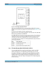
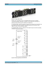
The R&S OSP-B103 module is supplied with power and controlled from the R&S OSP
via a single connector on the R&S OSP-B103 printed circuit board. The connection to
the R&S OSP is done via a single connection cable.
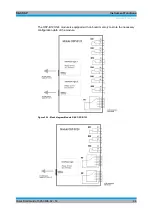
The R&S OSP-B103 module is equipped with an on-board memory to store the
necessary configuration data of the module.
Interface logic
Relay drivers
I
2
C memory
Interface
connector
Output Port
Ch6
To OSP frame
(cable W 5 or 6 or 7)
Ch3
Ch4
Ch5
Ch8
Ch13
Ch9
Ch10
Ch11
Ch12
Ch1
Ch2
Ch15
Ch16
Ch7
Ch14
Ch6
Ch3
Ch4
Ch5
Ch8
Ch13
Ch9
Ch10
Ch1
Ch2
Ch15
Ch16
Ch7
Ch14
+28 V
GND
Ch12
Ch11
Figure 5-18: Block Diagram Module R&S OSP-B103
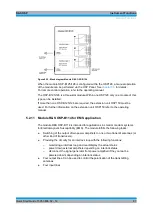
When the module R&S OSP-B103 is configured within the R&S OSP, a manual
operation of the module can be performed via the OSP Panel. See
chapter 3.3.9
details. For remote control operation and for details on the connector pin assignments,
refer to the operating manual.
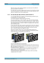
Depending on the required application, several modules of the R&S OSP-B103 type
can be installed in one R&S OSP.
In the R&S OSP frame a maximum of three modules is possible. If more than three
modules are required, the extension unit R&S OSP150 must be used. For further
information on the extension unit R&S OSP150 refer to the operating manual.
5.2.4 I/O Module R&S OSP-B104
The module R&S OSP-B104 is a digital I/O module for special applications in EMS
measurements.
Summary of Contents for OSP-B011
Page 132: ......


