R&S OSP
Getting Started
R&S OSP Panel Functions
Quick Start Guide 1505.3896.62 - 14
46
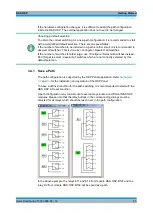
3.3.8.1 Setting the Output Pattern
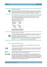
Clicking on one of the channel buttons in the output pattern field, the status of the
output channel can be changed.
24. An output channel marked in blue color indicates that the output channel is
switched to low level (GND). Switching is performed on an active low signal,
therefore the blue color indicates the active state.
25. An output channel marked in white color indicates, that the output channel is in
high impedance state. This is also the default after reset.
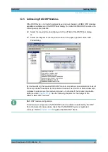
26. To take over particular channels of the output port into the path configuration, the
button left to the channels of the output pattern must be selected by clicking on
each button of the required outputs. The selected output channel is displayed in
green color. All output ports with selected (green) buttons are taken over into a
path configuration.
27. Pressing the Shift key while clicking on a relay button will toggle between
selecting all relays of this module and deselecting all of them.
28. Pressing this button sets the OPS-B103 outputs to the defined output pattern.
29. The actual setting of the R&S OSP-B103 outputs now is displayed in the output
pattern field (Ch1 to Ch16).
30. The hexadecimal representation of the output pattern is displayed in the OSP-
B103 dialog, too. Ch1 corresponds to the lowest bit, having the value 1, whereas
Ch16 is the highest bit, having the value 8000.
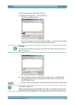
OSP-B103 dialog
When the dialog for operation of the R&S OSP-B103 module is opened, the actual
output pattern setting of this module is read back from the hardware and displayed.
I/O ports
Note that for I/O ports the hardware specification must be observed when connecting
external equipment. Refer to the operating manual for further information.
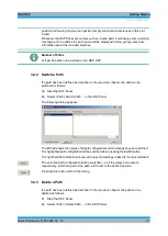
3.3.8.2 Reading the Input Pattern
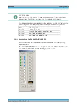
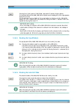
The input pattern of the R&S OSP-B103 can be read by one click.
31. Pressing this button reads the input pattern of the OPS-B103
The status of each input now is displayed in the input pattern field (Ch1 to Ch16).
The hexadecimal representation of the input pattern is displayed in the OSP-B103
dialog, too. Ch1 corresponds to the lowest bit, having the value 1, whereas Ch16 is
the highest bit, having the value 8000.
32. An input channel marked in blue color indicates that the input channel reads high level.
33. An input channel marked in white color indicates that the input channel reads low level.
Summary of Contents for OSP-B011
Page 132: ......


