R&S OSP
Instrument Functions
Graphical User Interface
Quick Start Guide 1505.3896.62 - 14
122
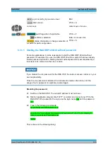
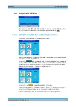
Pressing the key
STATUS
toggles the selection of the relay.
A selected relay (K1 and K2 in this example) is displayed with a green surrounding. All
selected relays are taken over into a path configuration.
A non selected relay is not considered when defining a path configuration.
The operation as described above applies to the following options of the R&S OSP
with similar relay configuration.
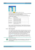
Option
Relay configuration
R&S OSP-B123
6 x SPDT relay, 18 GHz, terminated
1 x SP6T relay, 18 GHz, terminated
R&S OSP-B124
3 x SPDT relay, 18 GHz, terminated
3 x SP6T relay, 18 GHz, terminated
R&S OSP-B126
3 x SP6T relay, 18 GHz, terminated
R&S OSP-B129
1 x SP8T relay, 18 GHz, terminated
2 x SPDT relay, 18 GHz
Please note that for the modules R&S OSP-B121 to R&S OSP-B126 and R&S OSP-
B129 all relay types SPDT are counted starting with K1 whereas the SP6T types are
counted from K11 onwards.
5.3.11 Path Configuration
A very comfortable way to define the different switching paths required in a test setup
or in a system is the R&S
OSP feature “path configuration”. With suitable dialogs it is
easy to combine several relay positions of different R&S OSP modules in one path
information. If path switching is required, only the path configuration is called by its
name and the switching is performed more or less by a single command.
See also
chapter 3.4
for another approach to path configurations using OSP Panel.
In this chapter the functions related to path configurations are described based on
some example. Refer to the previous chapters for selecting switch positions or output
channel values.
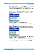
Choosing a default selection
To obtain the correct switching for a new path configuration, it is recommended to start
with a well-defined default selection. There are two possibilities described in the
following paragraph.
Summary of Contents for OSP-B011
Page 132: ......


