R&S OSP
Instrument Functions
Module Functions
Quick Start Guide 1505.3896.62 - 14
103
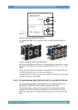
Module OSP-B116
Interface logic
Relay drivers
I2C memory
To OSP frame
(cable W 5 or 6 or 7)
Interface
connector
SMA
DPDT Relays
2
4
3
1
SMA
2
4
3
1
K1
K2
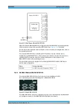
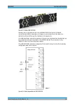
Figure 5-44: Block diagram Module R&S OSP-B116
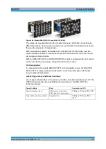
The module R&S OSP-B136 is equipped with N-connector relays.See following
pictures.
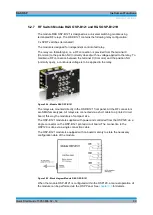
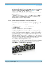
Figure 5-45: Module R&S OSP-B116 and R&S OSP-B136
When the module R&S OSP-B116/-136 is configured within the R&S OSP, a manual
operation of the module can be performed via the OSP Panel. See
chapter 3.3.9
details.
For remote control operation, for details in the application of this module and for the
connector pin assignments, refer to the operating manual.
The R&S OSP-B116/-136 is a one-slot module. Within one OSP base unit up to three
modules of this type can be installed.
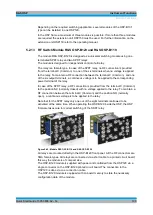
5.2.16 RF Switch Module R&S OSP-B101L/-B111xL and R&S OSP-B102L
The modules R&S OSP-B101L, R&S OSP-B111UL/VL and R&S OSP-B102L are
designed as a universal RF switch modules using latched relay types.
The latching relay type will maintain a choosen RF connection wether voltage is
maintained or not after switching is accomplished. The relay switching is done by
applying a voltage pulse to the relay; after that no energy is consumed by this relay
type.
Summary of Contents for OSP-B011
Page 132: ......

