R&S OSP
Instrument Functions
Graphical User Interface
Quick Start Guide 1505.3896.62 - 14
123
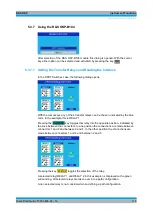
Go from the Main menu to the Configuration menu.
If the number of switches to be included in a path is rather small, it is recommended to
deselect all
switches. This is done by choosing “Deselect all switches”.
If the number of switches is rather large, chose “Select all switches” instead. Pressing
the key OK
will perform the related action.
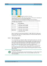
Now go back to the Main menu, and from there select “Manual Switching”. In the following
steps define all relay and output channel settings you want to include in the path
configuration by using the
FUNCTION
key. Don’t forget to select these relays and channels
using the
STATUS
key if you have started from a deselected switches configuration, or to
deselect the ones not required if you have started from a selected switches configuration.
A path configuration may consist out of several relays located on different R&S OSP
modules. Please note that the relay buttons in the corresponding dialogs must be
selected for all relays which should be taken over in the path configuration.
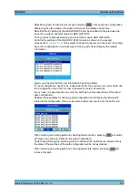
Perform the settings of the R&S OSP-B101 module as shown in the second
screenshot in
chapter 5.3.4
. This selects K11 to be in NO and K15 to be in NC
position.
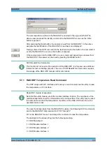
Then go back to the Main menu using the
MENU
key, and select the Path Switching menu.
If no path has been saved so far, the list shown in the dialog only contains undefined
paths. By default, on an R&S OSP130 there are ten paths which can be defined
(Panel_path_00 till Panel_path_01).
Summary of Contents for OSP-B011
Page 132: ......

