R&S OSP
Instrument Functions
Module Functions
Quick Start Guide 1505.3896.62 - 14
101
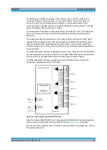
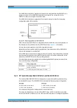
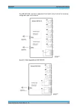
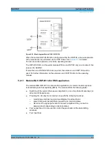
Figure 5-41: Block diagram Module R&S OSP-B129
When the module OSP-B129 is configured within the OSP120, a manual operation of
the module can be performed via the OSP Panel. See
chapter 3.3
For remote control operation refer to the operating manual.
The OSP-B129 is a one-slot module. Within one OSP120 up to three modules of this
type can be installed.
The OSP frame offers a maximum of three slots. If more than one OSP-B129 are
required, the extension unit OSP150 must be used. For further information on the
extension unit OSP150 refer to the operating manual.
The description above also applies to the following R&S OSP modules that have a
similar relay configuration:
Option
Relay configuration
OSP-B119
1 x SP8T relay, non terminated
2 x SPDT relay, non terminated
5.2.14 Power Sensor Module R&S OSP-PM-I
The module R&S OSP-PM-I allows to integrate a Power Sensor within the R&S OSP.
The module R&S OSP-PM-I includes one N-type feed-through connector and one USB
Adapter, both mounted in the modules front panel.
The module needs to be completed with a Power Sensor of the R&S family NRP-Zxx.
It is recommended to use a power sensor version with short cable (for example R&S
NRP-Z211 with Id. No. 1417.0409.04).
The module R&S OSP-PM-I is designed with base plate, where the Power Sensor
together with cable is fitted. The Power Sensor with its N-type connector is directly
screwed to the modules N-type feed-through connector. The Power Sensor is
controlled via USB interface. The Power Sensors USB connector (Odumac L-series
with 6 pins) is connected to the USB Adapter. The USN adapter serves as filter at the
same time.
Summary of Contents for OSP-B011
Page 132: ......

