Index-3
40 - [Skip Frequency Band] 5-7
41 - [Motor Overload Select] 5-8
42 - [Motor Overload Current] 5-8
43 - [Current Limit] 5-8
44 - [DC Hold Time] 5-8
45 - [DC Hold Voltage] 5-9
46 - [Input Mode] 5-9
47 - [Output Configure] 5-10
48 - [Output Threshold] 5-10
49 - [PWM Frequency] 5-10
50 - [Restart Tries] 5-10
51 - [Restart Time] 5-11
52 - [DB Enable] 5-11
53 - [S-Curve] 5-11
54 - [Clear Fault] 5-12
55 - [Memory Probe Address] 5-12
56 - [Reset Functions] 5-12
57 - [Program Lock] 5-12
58 - [Internal Frequency] 5-12
59 - [Frequency Select] 5-12
60 - [Zero Offset] 5-12
61 – 68 - [Preset Frequency 0-7] 5-13
69 - [Accel Time 2] 5-13
70 - [Decel Time 2] 5-13
71 - [IR Compensation] 5-14
72 - [Slip Compensation] 5-14
73 - [Reverse Disable] 5-14
74 - [Analog Select] 5-14
75 - [Analog Input Minimum] 5-15
76 - [Analog Input Maximum] 5-15
78 - [Compensation] 5-15
79 - [Software Current Trip] 5-15
80 - [Stall Fault Time] 5-15
81 - [PI Proportional Gain] 5-16
82 - [PI Integral Gain] 5-16
83 - [PI Process Reference] 5-16
resetting to factory defaults 5-12
potentiometer wiring 2-19
power wiring 2-2
precautions 2-2
terminal block specifications 2-3
precautions 1-1
preset frequencies 5-12
display mode 3-1
installation 3-4
key descriptions 3-2
program mode 3-1
removal 3-3
program lock 5-12
program mode 3-1
programming 5-1
example 5-2
reset to defaults 5-2
R
reflected wave protection 2-7
reflective wave
cable length 2-7
RWR (reflective wave reducer) 2-7
resetting default values 5-12
reverse key 3-2
RS-232 module B-5
S
S-Curve 5-11
select key 3-2
specifications A-1–A-3
380-460V AC input ratings A-1
control 2-9
electrical 2-2
environment 2-1
input power protection 2-5
installation 2-1
wiring 2-3
start key 3-2
start-up 4-1
stop key 3-2
storage temperature 2-1, A-2
T
terminal block
control wiring 2-9
specifications 2-9
TB1 2-2
TB2 2-2
TB3 2-2
fault descriptions 6-2
problems and corrective actions 6-3
V
Summary of Contents for Allen-Bradley 160 SSC Series
Page 12: ...1 6 Getting Started End of Chapter ...
Page 58: ...5 20 Parameters and Programming End of Chapter ...
Page 66: ...A 4 Specifications End of Chapter ...
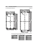
Page 75: ...Accessories and Dimensions B 9 Drilling Template A Figure B 10 ...
Page 76: ...B 10 Accessories and Dimensions Drilling Template B Figure B 11 ...
Page 82: ...C 6 CE Conformity End of Chapter ...
Page 87: ......

