Parameters and Programming
5-9
45
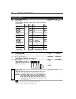
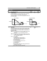
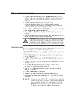
[DC Hold Voltage]
DC Voltage level applied to the motor during braking when P34 - [Stop Mode
Select] is set to either DC Injection Braking or Ramp to Stop mode.
If the current exceeds P43 - [Current Limit] the voltage applied to the motor will
be less than this setting.
0/115
1 Volt
0 Volts
46
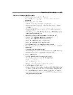
[Input Mode]
Configures the TB3 control inputs for various 3-wire or 2-wire control schemes.
Also enables/disables the Program Keypad Module, Remote Keypad Module or
CopyCat Keypad Module input control. See Chapter 2 for wiring diagrams and
descriptions of settings.
Important:
The method used to activate PI control is dependent upon Firmware
Version. Refer to 5-17 for PI Control Setup and Activation
instructions.
Important:
This parameter cannot be programmed while the drive is running.
In addition, power must be cycled or P56 - [Reset Function] must be
set to 2 for the change to take effect.
Settings: 0 = 3-wire control
➊
1 = 2-wire control
➊
2 = Program Keypad Module, Remote Keypad Module,
CopyCat Keypad Module, or Communication control
➊
3 = Momentary Run Forward/ Run Reverse control
➊
4 = 2-wire Accel/Decel control
5 = 2-wire Coast to Rest control
➊
6 = 2-wire TB3 Control/Keypad or Communication control
7 = 2-wire Frequency Select control
8 = 2-wire Preset control
➋
9 = 2-wire PI control
➋
➊
A contact closure on TB3 Terminal 7 and 8 is required for the drive
to respond to a Run command.
➋
Only available in Analog Signal Follower model.
0/9
Numeric
Value
0
Program Group
No.
Parameter Name/Description
Min./Max.
Range
Units
Factory
Default
DC Injection Braking Mode
Volts/Speed
Voltage
Time
Stop Command
Speed
[DC Hold Voltage]
[DC Hold Time]
Volts/Speed
Ramp-to-Stop Mode
Time
Stop Command
Vo
ltag
e
d
e
e
p
S
[DC Hold Voltage]
[DC Hold Time]
Summary of Contents for Allen-Bradley 160 SSC Series
Page 12: ...1 6 Getting Started End of Chapter ...
Page 58: ...5 20 Parameters and Programming End of Chapter ...
Page 66: ...A 4 Specifications End of Chapter ...
Page 75: ...Accessories and Dimensions B 9 Drilling Template A Figure B 10 ...
Page 76: ...B 10 Accessories and Dimensions Drilling Template B Figure B 11 ...
Page 82: ...C 6 CE Conformity End of Chapter ...
Page 87: ......

