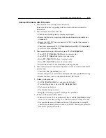
Parameters and Programming
5-15
75
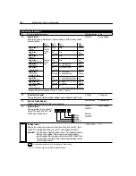
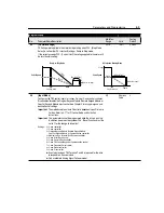
[Analog Input Minimum]
Important:
Do not adjust this parameter until setting P60 - [Zero Offset].
Sets the percent of analog input used to represent P32 - [Minimum Frequency].
If the minimum analog input equals minimum frequency, no action is needed. If
it is desired to adjust the analog input to equal P32 - [Minimum Frequency], use
P16 - [Analog Input] to adjust the analog input to the desired level using P60 and
then enter this value into P75.
Analog inversion can be accomplished by setting this value larger than P76.
Important:
This parameter cannot be programmed while the drive is running.
0.0/150.0
0.1%
0.0%
76
[Analog Input Maximum]
Important:
Do not adjust this parameter until setting P60 - [Zero Offset].
Sets the percent of analog input used to represent P33 - [Maximum Frequency].
If the maximum analog input equals maximum frequency, no action is needed. If
it is desired to adjust the analog input to equal P33 - [Maximum Frequency], use
P16 - [Analog Input] to adjust the analog input to the desired level using P60 and
then enter this value into P76.
Analog inversion can be accomplished by setting this value smaller than P75.
Important:
This parameter cannot be programmed while the drive is running.
0.0/150.0
0.1%
100.0%
78
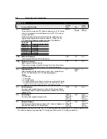
[Compensation]
Settings:
0 No compensation.
1 Some drive/motor combinations have inherent instabilities which are exhibited
as non-sinusodial motor currents. This setting attempts to correct this
condition.
2 Some motor/load combinations have mechanical resonances which can be
excited by the drive current regulator. This setting slows down the current
regulator response and attempts to correct this condition.
0 to 2
Numeric
value
0
79
[Software Current Trip]
This provides a software instantaneous current trip similar to the 300% hardware
current trip. This value is the percent above the P43 - [Current Limit] at which the
drive trips immediately. A setting of zero disables the Software Current Trip.
0/50%
1%
0%
80
[Stall Fault Time]
This selects the amount of time the drive must be in a stall condition before it
causes a stall fault.
0 = Normal stall time, approximately 60 seconds
1 = 2 times normal stall time
2 = 4 times normal stall time
3 = 6 times normal stall time
4 = 8 times normal stall time
5 = Stall fault disabled
ATTENTION:
Continuous operation at high currents caused by
a stall can cause motor damage.
0/5
Numeric
Value
0
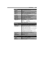
Program Group
No.
Parameter Name/Description
Min./Max.
Range
Units
Factory
Default
This parameter applies only to the Analog Signal Follower model.
Summary of Contents for Allen-Bradley 160 SSC Series
Page 12: ...1 6 Getting Started End of Chapter ...
Page 58: ...5 20 Parameters and Programming End of Chapter ...
Page 66: ...A 4 Specifications End of Chapter ...
Page 75: ...Accessories and Dimensions B 9 Drilling Template A Figure B 10 ...
Page 76: ...B 10 Accessories and Dimensions Drilling Template B Figure B 11 ...
Page 82: ...C 6 CE Conformity End of Chapter ...
Page 87: ......

