2-4
Installation and Wiring
Motor Branch Circuit Analysis
Short circuit and overload protection are requirements of any motor branch circuit.
Input power conditioning, CE conformance, reflective wave, capacitive current
coupling, and motor cable type are important considerations of drive applications.
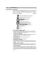
Branch Circuit Configuration
Figure 2.3
•
Branch Circuit Protective Devices
A motor branch circuit requires protection against excessive current. This
protection can be provided by a fuse, circuit breaker, or manual motor starter.
See Table 2.B for a detailed list of these options.
•
Input Power Conditioning
Certain conditions may exist that could damage a drive in the branch circuit.
See Table 2.C for an explanation of problems and solutions.
•
CE Conformance
See Appendix C for information on CE Conformance.
•
Motor Cable Types
See Table 2.D for recommended cable types.
•
Reflected Wave Protection
The use of a drive may result in increased peak-to-peak voltage at the motor.
See Table 2.E for an explanation of motor insulation limitations versus cable
lengths.
•
Capacitive Current Coupling
High speed voltage switching causes AC coupling from motor cables to ground
terminal/protective earth. See Table 2.F for cable length recommendations.
•
Overload Protection
All motor branch circuits require overload protection. The Bulletin 160 Drive is
UL listed to provide protection (IEC Class 10 overload) without an overload
relay. Separate overload relays are required in multi-motor applications or if the
drive kW (HP) rating is more than three times larger than the motor kW (HP)
rating.
Branch Circuit Protective Devices – See Table 2.B
Input Power Conditioning – See Table 2.C
160 SSC™
Motor Cable Types – See Table 2.D
Reflected Wave Protection – See Table 2.E
Overload Protection
CE Conformance – See Appendix C
Capacitive Current Coupling – See Table 2.F
Motor
Summary of Contents for Allen-Bradley 160 SSC Series
Page 12: ...1 6 Getting Started End of Chapter ...
Page 58: ...5 20 Parameters and Programming End of Chapter ...
Page 66: ...A 4 Specifications End of Chapter ...
Page 75: ...Accessories and Dimensions B 9 Drilling Template A Figure B 10 ...
Page 76: ...B 10 Accessories and Dimensions Drilling Template B Figure B 11 ...
Page 82: ...C 6 CE Conformity End of Chapter ...
Page 87: ......

