2-6
Installation and Wiring
Input Power Conditioning
The drive is suitable for direct connection to input power within the rated voltage
of the drive (see Appendix A). Listed in Table 2.C are certain input power conditions
which may cause component damage or reduction in product life. If any of the
conditions exist, as described in Table 2.C, install one of the devices listed under
the heading
Corrective Action
on the line side of the drive.
Important:
Only one device per branch circuit is required. It should be
mounted closest to the branch and sized to handle the total current
of the branch circuit.
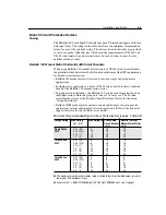
Input Power Conditions
Table 2.C
Motor Cable Types
A variety of cable types are acceptable for variable speed drive installations. For
many installations,
unshielded
cable is adequate, provided it can be separated from
sensitive circuits. As an approximate guide, allow a spacing of 1 meter (3.3 feet)
for every 10 meters (33 feet) of unshielded length. If you cannot separate motor
cables from sensitive circuits, or if you must run motor cables from multiple drives
(more than three) in a common conduit or cable tray,
shielded
motor cable is
recommended to reduce system noise.
Motor cables should be four-conductor with the ground lead and shield (if using
shielded cable) connected to the drive ground terminal and the motor frame ground
terminal.
Table 2.D provides the recommended wire type for both wet and dry installations
as defined by NEC 1996 (70-31). These recommendations are based upon a variety
of factors such as insulation thickness, susceptibility to moisture and susceptibility
to nicks and cuts during installation.
Recommended Cable Type
Table 2.D
➊
For input power voltages in excess of 264VAC, or motor cable distances greater than 15 meters
(50 feet), wire with XLPE insulation is recommended.
Input Power Condition
Corrective Action
Low Line Impedance (less than 1% line reactance)
• Check Line Impedance
• Line Reactor (See Appendix B)
• or Isolation Transformer
Available short circuit currents (fault currents) greater than
100,000 Amps
• Check Supply Transformer
• Line Reactor (See Appendix B)
• or Isolation Transformer
Greater than 120 kVA supply transformer
• Line Reactor (See Appendix B)
• or Isolation Transformer
Line has power factor correction capacitors
• Line Reactor (See Appendix B)
• or Isolation Transformer
Line has frequent power interruptions
• Line Reactor (See Appendix B)
• or Isolation Transformer
Line has intermittent noise spikes in excess of 6000V
(lightning)
• Line Reactor (See Appendix B)
• or Isolation Transformer
Condition
Insulation Type
Example
Dry
PVC
➊
THHN
XLPE
XHHW-2
Wet
XLPE
XHHW-2
Summary of Contents for Allen-Bradley 160 SSC Series
Page 12: ...1 6 Getting Started End of Chapter ...
Page 58: ...5 20 Parameters and Programming End of Chapter ...
Page 66: ...A 4 Specifications End of Chapter ...
Page 75: ...Accessories and Dimensions B 9 Drilling Template A Figure B 10 ...
Page 76: ...B 10 Accessories and Dimensions Drilling Template B Figure B 11 ...
Page 82: ...C 6 CE Conformity End of Chapter ...
Page 87: ......


