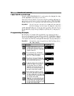
Parameters and Programming
5-7
38
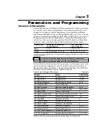
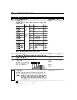
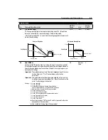
[Boost Select]
Sets the boost voltage and redefines the Volts per Hz curve. Settings 0 – 8 can
provide increased torque at low frequency. Settings 9 – 12 are used to reduce
energy consumption.
0/12
Numeric
Value
2
39
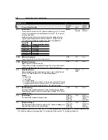
[Skip Frequency]
Works in conjunction with P40 - [Skip Frequency Band] creating a range of
frequencies at which the drive will not operate continuously.
0/240
1 Hz
240 Hz
40
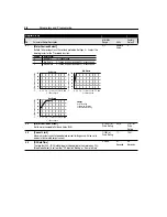
[Skip Frequency Band]
Determines the band around the
P39 - [Skip Frequency]
parameter. The actual
band width will be 2 times P40 - [Skip Frequency Band] - 1/2 the band above and
1/2 the band below. A value of zero will disable the skip frequency.
0/30
1 Hz
0 Hz
Program Group
No.
Parameter Name/Description
Min./Max.
Range
Units
Factory
Default
% [Base Frequency]
% [Base
Vo
ltage]
100
50
1/2 Base Volts
1/2
Base Freq.
9
10
11
12
0
50
100
1
8
See
Settings 1-8
Setting
Boost Voltage
(% of [Base Voltage])
0
1
2
3
4
5
6
7
8
0
2.5
5.0
7.5
10.0
12.5
15.0
17.5
20.0
Setting
Fan/Pump Curves
➊
9
10
11
12
45.0
40.0
35.0
30.0
➊
Break Point Voltages in percent of [Base Voltage]
tu
pt
u
O
y
c
n
e
u
q
e
r
F
r
e
ll
o
r
t
n
o
C
Frequency
Time
Skip
Frequency
Setting
Command
Frequency
2 x P40
[Skip Freq Band]
Setting
Summary of Contents for Allen-Bradley 160 SSC Series
Page 12: ...1 6 Getting Started End of Chapter ...
Page 58: ...5 20 Parameters and Programming End of Chapter ...
Page 66: ...A 4 Specifications End of Chapter ...
Page 75: ...Accessories and Dimensions B 9 Drilling Template A Figure B 10 ...
Page 76: ...B 10 Accessories and Dimensions Drilling Template B Figure B 11 ...
Page 82: ...C 6 CE Conformity End of Chapter ...
Page 87: ......

