A-2
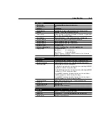
Specifications
All Drive Ratings
Table A.3
Input/Output Ratings
Output Voltage
Adjustable from 0 to Input Voltage
Output Frequency
Programmable from 0 to 240 Hz
Efficiency
97.5% Typical
Transient Protection
Standard 6 kV
Environmental Specifications
Enclosure
IP20
Ambient Temperature
0
°
C to 50
°
C
Storage Temperature
–40
°
C to 85
°
C
Relative Humidity
0 to 95% Non-Condensing
Vibration
1.0 G Operational — 2.5 G Non-Operational
Shock
15 G Operational — 30 G Non-Operational
Altitude
1,000 m (3,300 ft) without Derating
Control Inputs
Control Input Type
Dry Contact Inputs —
Drive has an internal 12V power supply that provides 10
mA typical current flow.
Alternate Inputs —
Accepts open collector/solid state inputs (sinking into the
drive) with maximum leakage current of 50
µ
A.
24V Inputs —
An optional 24V DC interface module allows use of 24VDC
sinking inputs (see ).
Start, Stop, Fwd/Rev
Configurable Inputs for Two- or Three-Wire Control
SW1, SW2, SW3
Preset Speed Model Only
Configurable Inputs for Control of 8 Preset Speeds and 2 Accel/Decel Times
Programmable Input
TB3-8 Can Be Configured to Select:
• Accel/Decel Times
• External Coast to Rest
• TB3 Control/Keypad or Communication Control
• Frequency Select
• Preset Speed
➊
Approvals and Standards Compliance
Approvals
Designed to Meet These Standards
FCC Class A
➋
and B
➋
, IEC 146-1-1, VDE 0871 and VDE 0875
Control Inputs —
Analog Signal Follower Only
External Speed
Potentiometer
1K to 10K Ohms, 2 Watts Minimum
4 – 20 mA Analog Input
250 Ohms Input Impedance
–10 to +10VDC
Analog Input
100K Ohms Input Impedance
Control Output
Programmable Output
(Form C Relay Contact)
Resistive Rating: 0.4A at 125VAC — 0.2A at 230VAC — 2A at 30VDC
Inductive Rating: 0.2A at 125VAC — 0.1A at 230VAC — 1A at 30VDC
➊
Analog Signal Follower only.
➋
With external components.
UL
®
LIST
ED 966X
IND CONT EQ
UL508C
UL
®
LIST
ED 966X
IND CONT EQ
C
CSA 22.2
AS/NZS 2064.1:1992
EMC Directive 89/336
LV:
EN 50178, EN 60204
EMC: EN 61800-3, EN 50081-1, EN 50082-2
Summary of Contents for Allen-Bradley 160 SSC Series
Page 12: ...1 6 Getting Started End of Chapter ...
Page 58: ...5 20 Parameters and Programming End of Chapter ...
Page 66: ...A 4 Specifications End of Chapter ...
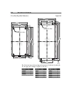
Page 75: ...Accessories and Dimensions B 9 Drilling Template A Figure B 10 ...
Page 76: ...B 10 Accessories and Dimensions Drilling Template B Figure B 11 ...
Page 82: ...C 6 CE Conformity End of Chapter ...
Page 87: ......


