Chapter
3
Program Keypad Module
The Program Keypad Module is located on the front panel of the drive. This module
is only operational when it is installed directly on the drive.
Features
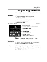
The Program Keypad Module provides the following features:
• 6-digit, 7-segment LED display
• Program Mode Indicator
• Five keys for programming and displaying drive parameters
• Three keys for control inputs to the drive
• Two directional LED indicators
Program Keypad Module
Figure 3.1
Display Mode
The drive always powers up in the Display mode. While in this mode you may
view all
read only
drive parameters, but not modify them.
Program Mode
You enter the Program mode by pressing the ESCape key. While in this mode,
you can edit Program Group parameters by pressing the SELect key. The Program
Mode Indicator will flash (see Figure 3.1) indicating the parameter value can be
changed. The Enter key (
↵
) must be pressed to write the new value to memory.
Refer to Chapter 5 for programming steps.
Parameter Number Display
Indicates which Display or Program Group parameter is active.
Parameter Value/Fault Number
Displays the parameter value or fault code number.
Program Mode Indicator
Flashes when in program mode.
Control Inputs and Indicators
Direction, Start, Stop (Stop is always active).
Important:
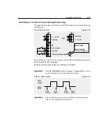
To activate Direction and Start inputs,
P46 - [Input Mode]
must be set to 2. Power must be cycled or
P56 - [Reset
Functions]
must be set to 2 for the change to take effect.
Summary of Contents for Allen-Bradley 160 SSC Series
Page 12: ...1 6 Getting Started End of Chapter ...
Page 58: ...5 20 Parameters and Programming End of Chapter ...
Page 66: ...A 4 Specifications End of Chapter ...
Page 75: ...Accessories and Dimensions B 9 Drilling Template A Figure B 10 ...
Page 76: ...B 10 Accessories and Dimensions Drilling Template B Figure B 11 ...
Page 82: ...C 6 CE Conformity End of Chapter ...
Page 87: ......


