5-10
Parameters and Programming
47
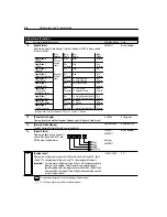
[Output Configure]
Configures the TB3 relay output functionality.
0/10
Numeric
Value
0
48
[Output Threshold]
Determines the on/off point for the TB3 output relay when P47 - [Output Configure]
is set to 6, 7, 8, and 10.
Setting
Ranges
6
0 to 240 Hz
7
0 to 180%
8
0 to 815 Volts
10
0 to 180˚
0/815
Numeric
Value
0
49
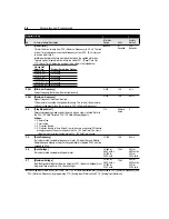
[PWM Frequency]
Carrier frequency for the PWM output waveform. The chart below provides
derating guidelines based on the PWM frequency setting.
Important:
Ignoring derating guidelines can cause reduced drive performance.
2.0/8.0
0.1 kHz
4.0 kHz
50
[Restart Tries]
Maximum number of times the drive will attempt to reset a fault.
Faults 03 – 20 will automatically reset according to this parameter setting.
0/9
Numeric
Value
0
Program Group
No.
Parameter Name/Description
Min./Max.
Range
Units
Factory
Default
Setting
Output Changes State When . . .
0
Drive Ready/Faulted
Energized and returns to shelf state when power is
removed or a fault occurs.
1
At Frequency
Drive reaches commanded frequency.
2
Motor Running
The motor is receiving power from drive.
3
Reverse
Drive is commanded to run in the reverse direction.
4
Motor Overload
A motor overload condition exists.
5
Ramp Regulated
The ramp regulator is modifying the programmed accel/
decel times to avoid an overcurrent or overvoltage fault
from occurring.
6
Above Frequency
The drive exceeds the frequency value set in
P48 - [Output Threshold].
7
Above Current
Drive exceeds the value set in P48 - [Output Threshold].
Important:
Value for P48 - [Output Threshold] must be
entered in percent of drive rated output current.
8
Above DC Bus Voltage
Drive exceeds the DC bus voltage value set in
P48 - [Output Threshold].
9
Retries Exhausted
Number of retries for P50 - [Restart Tries] is exceeded.
10
Above Power Factor
Angle
Power Factor angle exceeds the value set in
P48 - [Output Threshold].
1
2
3
4
5
6
7
8
84
86
88
90
92
94
96
98
100
% Output Current (A)
Carrier Frequency (kHz)
Summary of Contents for Allen-Bradley 160 SSC Series
Page 12: ...1 6 Getting Started End of Chapter ...
Page 58: ...5 20 Parameters and Programming End of Chapter ...
Page 66: ...A 4 Specifications End of Chapter ...
Page 75: ...Accessories and Dimensions B 9 Drilling Template A Figure B 10 ...
Page 76: ...B 10 Accessories and Dimensions Drilling Template B Figure B 11 ...
Page 82: ...C 6 CE Conformity End of Chapter ...
Page 87: ......


