5-8
Parameters and Programming
41
[Motor Overload Select
]
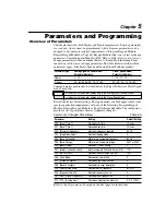
Bulletin 160 provides Class 10 overload protection. Settings 0 – 2 select the
derating factor for the I
2
t overload function.
0/2
Numeric
Value
0
42
[Motor Overload Current]
Set to motor nameplate Full Load Amps (FLA).
0.1/200% of
Drive Rating
0.01A
115% of
Drive
Rating
43
[Current Limit]
Maximum output current allowed before current limiting occurs. Value set in
percent of drive rated output current.
1/180% of
Drive Rating
1%
150%
44
[DC Hold Time]
The time that P45 - [DC Hold Voltage] will be applied to the motor when P34 -
[Stop Mode Select] is set to either “DC Injection Braking” or “Ramp to Stop.”
0.0/25.0
0.1
Seconds
0.0
Seconds
Program Group
No.
Parameter Name/Description
Min./Max.
Range
Units
Factory
Default
Setting
Derate Level
0
No Derate
10:1 speed range
1
Min. Derate
4:1 speed range, derate below 25% of base speed
2
Max. Derate
2:1 speed range, derate below 50% of base speed
Min Derate
0
80
100
60
40
20
% of [Overload Curent] Setting
% of [Overload Curent] Setting
% of [Overload Curent] Setting
No Derate
0
80
100
60
40
20
% of Base Speed
% of Base Speed
% of Base Speed
Max Derate
0
80
100
60
40
20
0
200
175
150
125
100
75
50
25
0
200
175
150
125
100
75
50
25
0
200
175
150
125
100
75
50
25
Settings
0 = No Derating
1 = Minimum Derating
2 = Maximum Derating
Summary of Contents for Allen-Bradley 160 SSC Series
Page 12: ...1 6 Getting Started End of Chapter ...
Page 58: ...5 20 Parameters and Programming End of Chapter ...
Page 66: ...A 4 Specifications End of Chapter ...
Page 75: ...Accessories and Dimensions B 9 Drilling Template A Figure B 10 ...
Page 76: ...B 10 Accessories and Dimensions Drilling Template B Figure B 11 ...
Page 82: ...C 6 CE Conformity End of Chapter ...
Page 87: ......

