RKF 130
Operating the piston filler
Version 1.1
Page 53 of 128
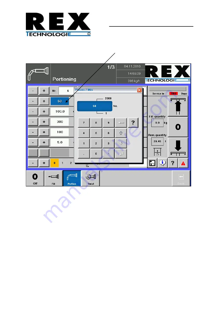
2. A number pad, on which the values can be changed directly, opens by simply pressing
the default setting (30).
Figure 16: Changing the default setting directly
Page 1: ... 2 3 Schematic diamgram in case of alternative operation 21 2 4 Image of the piston filler 22 2 5 Safety devices and their safety functions 24 3 Transport setup installation 25 3 1 Transport 25 3 2 Intermediate storage 26 3 3 Installation 26 3 4 Fuse protection 26 3 5 Aligning the machine 27 3 6 Space required for operation and maintenance 27 3 7 Dimensions weight and technical specifications 28 3...
Page 2: ...tup mask language options time and date 71 4 12 Screen settings 74 4 13 Recipe management 75 4 14 Note 78 4 15 Login 79 4 16 Info log 80 4 17 Service plan 81 4 18 Status report 82 4 19 Alarms faults 83 4 20 Troubleshooting 84 4 21 Emergency programme 86 4 22 Roasting and rotary pistons 87 4 23 Attaching the straight filling pipe and twisting pipe 89 4 24 Water drain 91 4 25 Attaching the twisting ...
Page 3: ...Maintenance and servicing 114 5 4 Maintenance and repair work 114 5 5 Lubrication 119 6 Troubleshooting and repair 121 6 1 Check list 121 6 2 Application technological error cause and error removal 123 7 De commissioning 125 7 1 De commissioning the piston filler 125 8 Explanations 126 8 1 Delivery explanation 126 8 2 CE Declaration of conformity RKF 130 127 8 3 Notes 128 ...
Page 4: ...n 41 Figure 11 Standby mode 46 Figure 12 Operating elements 48 Figure 13 Searching for a filling programme 50 Figure 14 Programme name keyboard field 51 Figure 15 Changing the default setting with or button 52 Figure 16 Changing the default setting directly 53 Figure 17 Filling the mask 58 Figure 18 Fill correction mask 59 Figure 19 Portioning mask 61 Figure 20 Portioning correction mask 62 Figure...
Page 5: ...Figure 36 Info log 80 Figure 37 Service plan 81 Figure 38 Alarm mask 83 Figure 39 Help mask 84 Figure 40 Alarm mask 2 85 Figure 41 Alarm mask 3 86 Figure 42 Installation sequence for roasting and rotary pistons 87 Figure 43 Attaching straight filling pipe 1 89 Figure 44 Attaching straight filling pipe 2 90 Figure 45 Water drain 91 Figure 46 Rotating casing holding device 92 Figure 47 Rigid casing ...
Page 6: ...ced here may neither be duplicated nor misused nor communicated to a third party without our prior approval Note the overall documentation for the RKF 130 piston filler comprises the following manual 1 The operating manual including spare parts documentation circuit diagram and oil flow diagram as well as 2 The CE declaration of conformity and the reply form machine acceptance log ...
Page 7: ... of 128 1 GENERAL INFORMATION MANUFACTURER REX Technologie GmbH Co KG Irlachstraße 31 5303 Thalgau Austria www rex austria com OPERATOR Name Address PIN location MACHINE MODEL Type Machine number Year of manufacture TRAINED PERSONNEL Name Name Name ...
Page 8: ...eading of the same is also made compulsory to this group of people Piston fillers subject to official inspection must be inspected before start of operation Determining the existence of a national or regional acceptance obligation is binding for the customer The manufacturer is excluded from all the liability claims in case of non compliance We recommend you to carefully read through this operatin...
Page 9: ... for proper operation or maintenance of the piston filler Every other use particularly forwarding abstraction re recording duplication or modification is not permissible without prior written approval We refuse any liability for damage to property for financial losses or for personal injuries if modified or external switching or control programmes including hardware and software are used as well a...
Page 10: ... Danger to persons 2 Pictograph for Danger to machine 3 Pictograph for Qualified electrician electronic technician required 4 Pictograph for Qualified mechanic required 5 Pictograph for Lubrication 6 Pictograph for Special tool required 7 Pictograph for Special instructions for the operating personnel ...
Page 11: ...ich can affect the safety adversely must be immediately eliminated or notified to the responsible qualified person The piston filler is solely meant for filling portioning and twisting off the filling material even in the frozen state however not colder than 4 C Any other use e g filling material that is colder than 4 C or for products that contain solid materials or materials having high toughnes...
Page 12: ... stopped and the changes must be notified to the responsible person No modifications extensions or reconstructions which affect the functioning and safety must be made to the piston filler without approval from the manufacturer Spare parts must fulfil the technical requirements specified by the manufacturer This is always ensured if original spare parts are used Prescribed deadlines or those speci...
Page 13: ...pment must be provided to the personnel Check regularly that the operating personnel work while taking into account safe operation and any possible dangers All the safety instructions and hazard warnings on the piston filler must be complete and in a legible condition In addition to this operating manual the general statutory and other binding regulations for accident prevention and environmental ...
Page 14: ...ing behaviour to the responsible person department Immediately shut down the machine in case of doubt and secure it against a re start switch off the main switch and lock it Before switching on the piston filler ensure that no person can be put at risk by starting the machine Special work and operation during maintenance repairs fault elimination etc Adhere to the setting maintenance and inspectio...
Page 15: ...nsured that it is re installed and checked for functioning immediately after the completion of the work The person in charge is responsible for this Make sure that operating and auxiliary materials as well as replacement parts are disposed in a safe and eco friendly manner Instructions for special dangers Electrical power Only use original fuses with prescribed currents and correct melting behavio...
Page 16: ...e and experience in the field of pneumatics may work on pneumatic devices Check all lines hoses and screw connections regularly for leaks and externally visible damage Immediately rectify any damage Oils greases and other chemical substances Adhere to product specific safety regulations when using oils greases and other chemical substances cleaning agents Be careful when working with hot operating...
Page 17: ... of 128 1 5 OPERATING RANGE AND DANGER AREA FOR THE OPERATING PERSONNEL RKF130 has the following danger areas see Figure 1 RKF 130 danger area Operating range Danger area Figure 1 RKF 130 danger area Type A B C D RKF 130 1277 1312 1080 1115 773 561 ...
Page 18: ...etely from stainless steel It stands on plastic feet which are adjustable in height and thus runs extremely quietly and smoothly when working The height adjustable feet allow balancing on an uneven floor and you can also comfortably clean the place where the machine stands thanks to clearance height The completely flat stainless steel surfaces simplify cleaning and also allow you to keep a visuall...
Page 19: ...n also fill products that are not intended for human consumptions However the machine does not have equipment for preventing risk of infection which comes from the processed products The subsequent use of the piston filler in accordance with clause 1 is strictly prohibited without prior implementation of cleaning and disinfection measures 3 In case of alternate use of the piston filler as per clau...
Page 20: ...nt due to unusual machine behaviour and thus an increased risk potential This piston filler may not be used for the following purposes without prior cleaning and disinfection Using products that are meant for human consumption and which are in accordance with the hygiene regulations if products have been processed previously which were not intended for human consumption or were not in accordance w...
Page 21: ... the piston filler for products meant for human consumption Using the piston filler for products meant for human consumption Cleaning disinfection The supplier s instructions must be adhered in this case Using the piston filler for products meant for human consumption after breaks 1 2 h The cleaning and disinfection work must be carried out in accordance with one of the cleaning schedules in chapt...
Page 22: ...mic loads that crop up during operation Even the environmental protection requirements are especially observed during the manufacturing process The piston filler stands out due to the extremely quiet and smooth running The external machine parts are made of stainless steel or non corroding material The complete machine surface is specially treated for the purpose of easy cleaning and maintenance B...
Page 23: ...RKF 130 Description of the machine Version 1 1 Page 23 of 128 Machine depiction 1 2 3 5 6 7 11 10 4 9 12 3 13 Figure 3 Functional elements and their arrangement on the piston filler ...
Page 24: ...stic 13 Rigid casing holding device optional Stainless steel plastic 2 5 SAFETY DEVICES AND THEIR SAFETY FUNCTIONS All the safety devices must be checked before the work is started The relevant accident prevention regulations of the country in which the machine in being operated are decisive Main switch Figure 8 Main switch page 39 Main switch in position 0 separates the piston filler completely f...
Page 25: ...ng when transporting Set up and align the piston filler at the workplace Unscrew and screw in the feet of the machine for aligning If the piston filler has been ordered with the optionally available machine wheels they are enclosed with the machine accessories For the installation of the rollers the piston filler must be lifted the machine feet must be removed and the rollers must be screwed on to...
Page 26: ...itly authorised for the same by the manufacturer The piston filler should be placed on a strong flat and easy to clean floor The floor gradient must be a maximum of 3 and the permissible floor loading must at least be 5 kN m The installation location must comply with the local hygiene and workplace regulations The intensity of illumination must be at least 300 LUX The piston filler is delivered su...
Page 27: ...height cannot be aligned if rollers have been installed 3 6 SPACE REQUIRED FOR OPERATION AND MAINTENANCE The piston filler must be easily accessible for cleaning and maintenance of all sides For this a free space of at least 0 5 m to the piston filler from all sides is necessary for this alternatively sufficient free elbowroom is required such that the necessary activities for operating cleaning m...
Page 28: ...8 Version 1 1 3 7 DIMENSIONS WEIGHT AND TECHNICAL SPECIFICATIONS Figure 5 RKF 130 Type RKF 130 Cylinder capacity 30 litres Filling pressure 15 bar Portioning speed Maximum 350 port min Weight 400 kg Connected wattage 3 5 KW Clipper connection Optional ...
Page 29: ...ied out only by qualified electricians or by instructed experts who have been trusted with the mode of operation in compliance with the valid nations regulations e g EN 60204 Safety measures and safety equipment must comply with the valid national regulations and standards e g EN 50178 and EN 60204 The leakage current can be greater than 3 5 mA AC and 10 mA DC Nominal voltage of the piston filler ...
Page 30: ...ection the polarity of the phases in the connection line must be reversed Attention The hydraulic pump should not run in the wrong direction for a long time otherwise it will get damaged If it is determined that the hydraulic pump of the piston filler is running in the incorrect rotating direction it must be switched off immediately and the polarity of the connection line must be reversed All the ...
Page 31: ...ry pistons Insert the roasting piston in the correct position in the roasting cylinder and tighten the piston screw at the piston rod using the lifter tool Insert the rotary piston in the correct position in the rotary piston cylinder Put the cover seal in the roasting cylinder Installing the filling or twisting pipe If the piston filler is equipped only for portioning the filling pipe must be scr...
Page 32: ... and limbs The following can be at a risk because of the filling material the operator user the environment at the installation location of the piston filler the piston filler itself The following must be kept at a distance from the piston filler youths or trainees without supervision persons not instructed to operated the machine persons who are not trusted with the operating manual and safety re...
Page 33: ...ntact and functional The product to be used complies with the intended use refer to section 2 2 Use Defective or worn parts adversely affect the safety and must be replaced immediately According to UVV Meat Processing Machines VBG 19 insured persons must check the functional efficiency of safety equipment per working day before starting the meat processing machines Any faults must be immediately n...
Page 34: ...specific work programs Explaining the programming on the basis of chapter 4 4 Description of the touch control system Saving set programs in the electronic system explaining the accessories used explaining every work step for cleaning piston fillers on the basis of chapters 5 1 and 5 2 explaining the maintenance work on the basis of chapters 5 3 and 5 4 filling the piston filler Starting the produ...
Page 35: ...d complies with the intended use refer to chapter 2 2 Use No person is present in the area of moving machine parts No foreign matter wood cloth tools etc is present in the roasting cylinder or in the rotary piston of the piston filler Operating personnel is suitable and is trusted to work with the piston filler The operating personnel is familiar with the safety regulations The machine is in prope...
Page 36: ...h fingers with or without gloves The touch screen must not be operated using pointed sharp metallic objects and also not with ballpoint pens or pencils On button I The piston filler is started by pressing the I button Off button 0 A dialog field opens on pressing the Off button in which the switch off of the piston filler has to be confirmed again ...
Page 37: ...d now apply not only to the knee lever but that a switch which is connected to the connections 3 and 4 of the clip machine power point e g a clip machine having a start switch gives rise to the same reactions Knee lever switch Figure 6 Knee lever switch The knee lever has the following function depending on what is pre selected in the control system Knee lever blocked ...
Page 38: ... The piston filler starts filling as soon as the knee lever is pressed for the first time The knee lever must be tapped to stop the straight filling and portioning Press it once again to restart The advantage of this knee lever function is that it does not have to remain pressed constantly in case of larger straight filling quantities or larger number of portioning pieces Piece specification It is...
Page 39: ...ipper power point The power point must be used for connecting different clip machines or REX attachments Figure 7 Clipper power point Main switch The main switch opens or closes the voltage supply of the piston filler to the power supply network Figure 8 Main switch ...
Page 40: ...F THE TOUCH SCREEN 11 12 21 Figure 9 Pre cleaning mask On starting the piston filler you automatically reach the pre cleaning mask if the roasting cylinder cover is open The control system automatically switches to the selected operating mode on closing the roasting cylinder cover ...
Page 41: ...0 19 18 17 Figure 10 Touch screen On the pages 40 83 the numbers in brackets refer to Figure 10 Touch screen 1 The respective operating mode icon is displayed in this field 2 The selected operating mode or information mask is displayed 3 The theoretical filling performance in kilograms per hour Kg hr is displayed 4 Time display ...
Page 42: ... alarm mask The button blinks if at least one unacknowledged alarm is present in the piston filler 17 Back button for leaving the respective background page 18 Selection button for help texts 19 Selection button for opening the information page 20 Button for saving the set programme in the main memory A dialog field opens on pressing this button in which saving of the respective programme has to b...
Page 43: ...ification mode 28 Selection button for reducing the selected value 29 Selection button for increasing the selected value 30 Selection button for the desired speed value 31 Display of the current programme number On pressing in the display field a number dialog box opens in which the programme can be directly selected 32 Display of the current sausage name the name can be changed here with the help...
Page 44: ...oated protective foil This means that mechanical loads particularly metal parts falling down tool accessories can cause the screen glass to break or result in holes in the protective foil and thus give rise to expensive repairs which are not included in the warranty payments Refer to section 1 4 and 4 Attention Wait for at least 30 seconds between switching off the piston filler and switching it o...
Page 45: ...nd to the connected clip machine to stop the sausage This procedure is repeated as long as the knee lever is pressed pay attention to the single permanent portioning Twisting off The piston filler produces a certain quantity of sausage meat depending on the programme data and then gives the command to the connected twisting equipment to stop the sausage twisting off This procedure is repeated as l...
Page 46: ...piston filler After the piston filler has been connected to the network using the main switch it takes approximately 30 seconds to boot the control system The screen is largely black in the process and the control system then goes into the standby mode Standby mode Figure 11 Standby mode ...
Page 47: ...e button 20 The set values are saved in the set programme location by pressing the Save button Info button 19 Various settings such as Screen setting Recipe management etc can be called under the Info mask Help button 18 All the necessary help and information texts of the respective machine functions can be called in the Help mask Alarm button 16 Any imminent machine alarms can be read or acknowle...
Page 48: ...RKF 130 Operating the piston filler Page 48 of 128 Version 1 1 16 26 20 19 18 17 Figure 12 Operating elements ...
Page 49: ...n button The respective value or name is accepted or the procedure is confirmed by pressing the confirmation button Help button A dialog field opens for the user by pressing the Help button where he she receives information for the selected procedure Abort button The respective procedure is aborted and not accepted by pressing the Abort button Delete button The respective value in the steps can be...
Page 50: ...tion 1 By pressing the buttons 28 or 29 the programme number from 1 to 200 can be changed in steps 2 A selection window opens on pressing field 31 The desired programme or the free programme location can be directly selected here 31 Figure 13 Searching for a filling programme The selection window can be moved up using the scroll bar right ...
Page 51: ...g the piston filler Version 1 1 Page 51 of 128 3 Entering the programme name A keyboard field opens on pressing the field 32 using which the desired programme name can be entered Figure 14 Programme name keyboard field ...
Page 52: ...piston filler Page 52 of 128 Version 1 1 4 4 5 Changing default settings 1 The default setting can be changed in steps by pressing the respective 28 or 29 button 30 28 29 Figure 15 Changing the default setting with or button ...
Page 53: ...Operating the piston filler Version 1 1 Page 53 of 128 2 A number pad on which the values can be changed directly opens by simply pressing the default setting 30 Figure 16 Changing the default setting directly ...
Page 54: ...the piston filler Page 54 of 128 Version 1 1 Keyboard input field 3 The respective setting ranges for the selected value are displayed above in the numeric field Set value Maximum default setting Minimum default setting ...
Page 55: ...st portioning In addition the weight correction value in the respective correction mask must be taken into account 4 5 3 Filling break Time that should pass between the filled portions setting range from 0 3000 ms if the portioning chain has not been interrupted by pressing the knee lever pay attention to the 1 2 3 knee lever position This value is insignificant if every portioning is started by p...
Page 56: ... on Portioning interruption deactivated If the knee lever is released in case of single portioning when a portion is being filled or tapped once again in case of permanent portioning piece specification the conveying system does not stop immediately in the normal mode but fills the already started portion till the end Portioning interruption active The filling process stops immediately if the port...
Page 57: ...nd clip impulse is equal to the duration of the 1st clip impulse 4 5 16 Correcting the last portion This value with the unit cm is then deducted from or added to the capacity of the last portion setting range of 9999 9 cm to 9999 9 cm 4 5 17 Pre selection weight This is for setting the amount of weight to be produced Once the desired quantity has been reached production is stopped and a dialog ope...
Page 58: ...an be selected with the help of the respective button Speed 30 Knee lever position single 34 or permanent portioning 35 5 Weight acceptance for the portioning or twisting off programme special function Filled weight 37 Reset 38 the display in the field 37 filled weight Accept the filled weight 37 in the portioning programme 39 Accept the filled weight 37 in the twisting off programme 40 31 32 30 3...
Page 59: ... 25 again The standard values of the parameter can be changed for optimisation 7 The following value can be selected with the help of the respective button Acceleration ramp for roasting piston 36 8 You again return to the main mask by pressing the Fill button 25 or the Back button 17 again 36 Figure 18 Fill correction mask ...
Page 60: ...og field The settings changed right now are overwritten in the currently selected programme by pressing the Save button A dialog field opens on pressing the Save As button The following options are available here selecting an existing programme and overwriting creating a new programme ending the process by pressing the Abort button On pressing the Abort button you return to the filling programme w...
Page 61: ...sage name 32 4 The following values can be selected with the help of the respective button Speed pc min or Filling weight Filling break Clipper impulse Adding the 1st portion Knee lever position single portioning 34 permanent portioning 35 or piece specification 41 31 32 41 35 34 24 Figure 19 Portioning mask 5 The first portioning correction mask opens on pressing the Portioning button 24 again ...
Page 62: ...ues can be selected with the help of the respective buttons Acceleration ramp for roasting piston Weight correction Lead or lag of the clip signal Portioning interruption 7 You get to another correction mask on pressing the Portioning button 24 again You return to the main mask on pressing the Back button 17 24 17 Figure 20 Portioning correction mask ...
Page 63: ...the respective buttons Speed of the 1st portion Correcting the last portion Weight preselection Delay in the 2nd clipper impulse Moving depending on the speed Stop in pairs 8 You again return to the main mask by pressing the Portioning button 24 or the Back button 17 again 24 17 Figure 21 Portioning correction mask 2 ...
Page 64: ...og field The settings changed right now are overwritten in the currently selected programme by pressing the Save button A dialog field opens on pressing the Save As button The following options are available here selecting an existing programme and overwriting creating a new programme ending the process by pressing the Abort button On pressing the Abort button you return to the filling programme w...
Page 65: ...Select the programme location 31 3 Assign the sausage name 32 4 The following values can be selected with the help of the respective buttons Speed pc min or Filling weight Number of twist offs Adding the 1st portion Knee lever position single portioning 34 permanent portioning 35 or piece specification 41 31 32 41 35 34 23 Figure 22 Twisting off mask ...
Page 66: ...n 6 The following values can be selected with the help of the respective button Acceleration ramp for roasting piston Weight correction Twisting off position Filling position Additional twisting of the 1st portion Portioning interruption 7 You get to another correction mask on pressing the Twisting off button 23 again You return to the main mask on pressing the Back button 17 24 17 Figure 23 Twist...
Page 67: ...ith the help of the respective buttons Speed of the 1st portion Correcting the last portion Weight preselection Moving depending on the speed Stop in pairs 9 You again return to the main mask by pressing the Twisting off button 24 or the Back button 17 again 24 17 Figure 24 Twisting off correction mask 2 ...
Page 68: ...og field The settings changed right now are overwritten in the currently selected programme by pressing the Save button A dialog field opens on pressing the Save As button The following options are available here selecting an existing programme and overwriting creating a new programme ending the process by pressing the Abort button On pressing the Abort button you return to the filling programme w...
Page 69: ...ice information column In addition the remaining operating hours or days till the next servicing of the piston filler can be read A dialog field where additional information is displayed opens on pressing in the service information field The set machine type is displayed in the Machine type column The machine manufacturer is displayed in the left column under Accessibility Optionally the address o...
Page 70: ... after the Align pipe button is pressed in the Info mask Info mask Figure 26 Align pipe special function If the knee lever is pressed the pipe starts rotating which makes the alignment possible The twisting pipe stops if the knee lever is released This function can be aborted using the Abort button and Back button 17 ...
Page 71: ...E OPTIONS TIME AND DATE Setup mask The machine operator can configure settings local time date etc in the setup mask In addition the desired language can be selected in the Language options Important information such as machine number machine code is also stored there Setup mask Figure 27 Setup mask ...
Page 72: ...ston filler Page 72 of 128 Version 1 1 Language options A window in which the desired language can be selected right to add languages reserved opens on pressing the display field of the set language Figure 28 Language options ...
Page 73: ... which the desired date or the local time can be set opens on pressing the display field of the date or time Figure 29 Setting the date Figure 30 Setting the time The other settings or changes such as versions release code and screen background lighting can only be configured by authorised REX dealers ...
Page 74: ...ings mask Buttons in the operating mode bar can be faded out or superimposed in the Operating mode column Portioning 24 Twisting off 23 2 Clipper impulse Weight meter Weight acceptance You can select in Settings whether the date 5 the time 4 and kilo hour 3 must be superimposed in the main mask The Logo column is reserved for the authorised REX dealers or technicians for settings ...
Page 75: ... 4 13 RECIPE MANAGEMENT On pressing Recipe Management a mask opens in which all the set filling programmes can be displayed sorted deleted and renamed as well as programme specific production data can be read Recipe management mask Figure 32 Recipe management mask ...
Page 76: ...me data on data carriers by connecting a USB stick to the CPU control system interface meant for it As soon as a recipe has been selected by clicking the Process button can be pressed and the following options are available as well Delete Deletes the selected recipe from the list Statistics Various values such as the total number of sausages produced can be inferred here Figure 33 Recipe statistic...
Page 77: ... additional programme mask it appears as the first one can be viewed in the respective programme mode filling portioning twisting off after activating and selecting the programme numbers for the preferred setting parameter A selection window in which the possible setting parameters can be selected opens on selecting the display line It must be saved using the Save button after selection ...
Page 78: ...RKF 130 Operating the piston filler Page 78 of 128 Version 1 1 4 14 NOTE Different notes can be saved in this mask Figure 35 Note ...
Page 79: ...RKF 130 Operating the piston filler Version 1 1 Page 79 of 128 4 15 LOGIN This mask is reserved for the authorised REX dealers or technicians for settings ...
Page 80: ... Page 80 of 128 Version 1 1 4 16 INFO LOG The complete process all the executed work steps is recorded here The data is saved in chronological order This data is important for the technician if an error message appears Figure 36 Info log ...
Page 81: ...rk that has already been carried out must have been carried out at the prescribed intervals refer to chapter 5 4 Maintenance and repair work As soon as the service interval display shows a due servicing an authorised service technician must execute the maintenance work and save it Figure 37 Service plan Attention The service interval display 8 is reset to the main mask after the servicing and main...
Page 82: ...iller Page 82 of 128 Version 1 1 4 18 STATUS REPORT A status report regarding the error can be released in case of a programme error The report is saved automatically Your authorised dealer can read this data and process it further ...
Page 83: ...ges The piston filler interrupts the operation for every single pending error message and opens the alarm mask independently or by pressing the alarm button Figure 38 Alarm mask All the faults along with the alarm number the time as well as an alarm description are displayed in this alarm mask ...
Page 84: ...nding fault For every alarm the possible cause including help for troubleshooting is saved in the Help button Help button A window containing instructions for possible causes of the fault including their elimination is displayed after pressing the button Window with instructions for causes of the fault Figure 39 Help mask ...
Page 85: ...RKF 130 Operating the piston filler Version 1 1 Page 85 of 128 The error must be acknowledged after it has been eliminated Figure 40 Alarm mask 2 ...
Page 86: ...ht next to the delete button Figure 41 Alarm mask 3 4 21 EMERGENCY PROGRAMME If the measuring ruler of the roasting piston is defective there is an option of operating the piston filler in an emergency programme The roasting piston can be driven in the emergency programme only by actuating the knee lever Attention Please contact your authorised REX dealer immediately for eliminating the fault ...
Page 87: ...on 1 1 Page 87 of 128 4 22 ROASTING AND ROTARY PISTONS Installation of the correct parts in the correct sequence is a prerequisite for RKF 130 to function properly 7 8 6 5 4 3 2 1 Figure 42 Installation sequence for roasting and rotary pistons ...
Page 88: ...fting tool The roasting piston must be fit in the correct position in the roasting cylinder and screwed to the piston rod 4 2 Piston screw Tighten with a lifter pos 6 5 3 Cover seal Lubricate slightly with grease and place it in the intended groove 6 See remarks Lifter Helps t tighten the piston screw 7 See remarks Rotary piston seals Attached to the rotary piston 8 4 Rotary piston Insert the rota...
Page 89: ...rsion 1 1 Page 89 of 128 4 23 ATTACHING THE STRAIGHT FILLING PIPE AND TWISTING PIPE Filling pipes 1 can be easily screwed on to the outlet 3 of the piston filler using the filling pipe nut 2 1 2 3 Figure 43 Attaching straight filling pipe 1 ...
Page 90: ...RKF 130 Operating the piston filler Page 90 of 128 Version 1 1 Then press the locking device 4 and tighten the filling pipe nut 5 with the twisting key 5 4 5 Figure 44 Attaching straight filling pipe 2 ...
Page 91: ...RKF 130 Operating the piston filler Version 1 1 Page 91 of 128 4 24 WATER DRAIN The water drain pipe 1 remains unlocked The rotary pistons are sealed 1 Figure 45 Water drain ...
Page 92: ...the casings by hand or attach a casing holding device The productivity can be increased by using a casing holding device 3 1 4 2 Figure 46 Rotating casing holding device Pos Installation sequence Name Remarks 1 1 Twisting pipe Attach to the outlet of the twisting drive 2 2 Twisting nut Tighten it firmly with the provided accessory key 3 3 Rotating casing holding device Place in the twisting flange...
Page 93: ...8 The following steps should be followed 1 Switch off the piston filler with the Off button 2 Place the casing holding device carefully on the twisting flange 3 Turn the lock of the casing holding device to the right till the limit stop and tighten the lock screw ...
Page 94: ...ion 1 1 4 Screw the twisting pipe to the outlet The twisting drive can be secured against twisting by pressing the lock button on the twisting drive The twisting pipe can fixed using the accessory key 5 Use the casing brake set in the casing holding device ...
Page 95: ...al casing rollers can be attached to or removed from the casing holding device depending on the use of artificial or natural casings The height of the artificial casing rollers must be set individually depending on the casing type used 9 The casing brake can be adjusted by using the tool key accessory This influences the strength of the filled casing cover ...
Page 96: ...e depending on the skill of the operator The productivity can be increased by using a casing holding device 3 1 4 2 Figure 47 Rigid casing holding device Pos Mounting sequence Name Remark 1 1 Twisting off tube Attached to the run out of the twisting off gear 2 2 Twisting off master Tightening permanently with accessory key provided 3 3 Rigid casing holding device Fit in the twisting off flange pro...
Page 97: ...ller with the off button 2 Fit the casing holding device carefully on the twisting off flange 3 Seal casing holding device to the right till stop rotate and tighten the sealing screw 4 Screw in the adjusting ring on the casing holding device Attention The adjusting ring diameter must coincide with the twisting tube diameter ...
Page 98: ...d the twisting off gear against twisting by pressing the locking button on the twisting off gear Fasten the twisting off tube with the accessory key 6 The distance to the braking lip can be adjusted by twisting the adjusting ring on the casing holding device This influences the resistance of the filled casing cover ...
Page 99: ...9 9 9 9 9 15 17 15 16 17 14 16 16 18 19 18 20 16 18 10 10 10 10 10 19 21 17 23 18 20 20 22 11 11 11 12 11 11 23 23 26 18 20 20 22 12 12 12 12 26 26 32 18 20 20 22 14 14 14 14 14 26 28 28 32 22 24 24 26 16 16 16 16 16 30 32 26 28 28 30 18 18 18 18 18 34 28 30 20 20 20 20 20 36 40 43 38 40 36 30 32 32 34 34 36 32 35 22 22 22 22 22 43 47 52 38 42 36 38 35 37 37 40 40 24 24 24 24 24 58 42 45 50 40 43 ...
Page 100: ...ted wet Salted dry Pre process On the previous day Rinse the casings well with cold water squeeze a little and store in a cool place overnight On the day of processing Soak the casings in hot water 37 C 60 minutes Soak the casings in hot water 37 C 30 60 minutes Improve sliding properties With additives e g sodium bicarbonate baking soda amount to be added 2 3 tablespoons in 5 litres of water 37 C...
Page 101: ...lements and their arrangement on the piston filler page 23 The start of the industrial operation of the piston filler takes place as follows Following the general safety instructions e g according to the chapters 1 4 and 4 1 Fill the product in the roasting cylinder 4 and close the roasting cylinder cover 10 Attention Only use products which correspond to the requirements as per chapter 2 2 Use ...
Page 102: ...nition of possible disturbance sources Hence during the operation the person working on the piston filler should observe the machine as well as the periphery also If any anomalies such as Strange noises Unusual vibrations Irregular running of the piston filler Noticeable warming up of the piston filler are determined then report immediately to the supervisor Attention Upon re closing the roasting ...
Page 103: ...ff in dangerous situations 1 Switch off using the main switch Figure 8 Main switch page 39 Switch on the main switch immediately if any danger of injuries or damages to the piston filler exists 2 Switching off with the motor protection circuit in the control box Activating the motor protection circuit also results in switching off the piston filler The hydraulic pumps and the twisting off motor ar...
Page 104: ... Determine the cause if required consult specialised staff for determining it Switch on piston filler using the on button chapter 4 2 Operating elements function 3 In case of switch off due to unconfirmed fault report Consult an authorised REX contract dealer or a REX technician for testing at all costs Determine and remove the cause of the fault report Reconnect the piston filler only through a t...
Page 105: ...ons The piston filler should be switched off immediately at the end of production This takes place advantageously in the sequence Switch off the piston filler using the off button 4 2 Operating elements function Switch off the main switch position 0 Figure 8 Main switch page 39 Switching off the main switch is absolutely required for cleaning The piston filler can however be switched on at the mai...
Page 106: ...aging the electrical and mechanical parts Never direct the abrasive blast cleaning on the following units Control panel touch control Area of mechanical bearings Other electrical devices such as clamp or cable lead ins external device sockets Louvre on the floor of the piston filler All the visible seals Do not process polished metal surfaces with abrasive medium danger of eroding the anti corrosi...
Page 107: ...are indispensable for the good quality of the product avoiding biological contaminations of the product fulfilling appropriate hygiene regulations conserving the piston filler s value Cleaning can be done with alkaline alternatively with acidic solutions The appropriate suitable medium is alternatively applicable or must be selected corresponding to the nature of the material of the machinery comp...
Page 108: ...te Button Plastic Plastic No chemicals No chemicals Piston and piston cover seal Figure 42 Installation sequence for roasting and rotary pistons page 87 Plastic No chemicals 5 Machine body Stainless steel alkaline acid 6 Toggle lever Plastic No chemicals 12 Casing holding device Plastic No chemicals 5 2 3 Cleaning agent Using a high pressure cleaner with the following accessories is recommended La...
Page 109: ...ming device or brushes or in tub Rinsing Water having drinking water quality 60 C Low pressure 30 bar manual Low pressure cleaning device water hose Inspecting cleanliness visual Clean when required Disinfecting 0 5 2 solution of e g Henkel P3 topax 99 Henkel P3 topax 91 Goldschmidt TEGO 2000 TEGO IMC Spraying foaming application time as per product data sheet High pressure cleaner low pressure de...
Page 110: ...allow foaming or manual application time 15min High pressure cleaner low pressure foaming device spray pistol or brush for removing lime scales Attention In case of parts not made from stainless steel Strictly follow the instructions of manufacturer Rinsing Water having drinking water quality 60 C Low pressure 30 bar manual Low pressure cleaning device water hose Inspecting cleanliness visual Clea...
Page 111: ...socket exists The protection cap should be attached after removing the connection cable from the clipper socket Figure 7 Clipper power point page 39 If work was done with a filling tube then loosen filling tube master and withdraw with the filling tube Withdraw the rotating piston Withdraw roasting piston Loosen piston screw with lifting fork Screw in the lifting fork in the roasting piston Withdr...
Page 112: ... main switch Pre rinse external machine body machine run out roasting cylinder cover roasting cylinder rotating piston cylinder and also bearing and drive shaft for rotating piston with hot water and with suitable tool high pressure cleaner brush scraper trowel water hose Thoroughly clean machine parts especially the parts contacted by the product individually with cleaning solution as per the cle...
Page 113: ...nfectant solution as per cleaning plan and using a suitable tool high pressure cleaner low pressure foaming device spray pistol brush etc The application time given in the product data sheet of the manufacturer of cleaner and disinfectant and other usage instructions should be followed accurately Rinse all disinfected parts with drinking water Dry all treated parts if required with sterile and oil...
Page 114: ... or its parts This prohibition is also enclosed with the control hardware and software side wiring and the configuration of devices The warrantee deed from the machine manufacturer or his agencies is cancelled in case of non compliance If the cover of the switch box was opened then the cover seal should be implicitly tested for leak proof closure and should be renewed if required Further it must b...
Page 115: ...ge 5 4 2 Weekly maintenance every 40 working hours Generally the piston filler has not provided for any lubricating points with the exception of the rotating casing holding device This is marked in colour and can be found immediately by the information signs The following is applicable for these cases Lubricate as per separate lubricating instructions Insert approx 0 1 cm grease per lubricating po...
Page 116: ...hrs day however at least yearly Allow maintenance work to be executed only by REX technicians or by trained technicians of our authorised contract dealers The works to be executed during maintenance are always listed in the service template of our touch control The control refers to the service work to be executed in intervals 4 17 ...
Page 117: ...em with the help of complete servicing lists for maintenances and or they should be entered in the touch control system 5 4 4 5 yearly maintenance work All electric clamps in the control box must be tightened by a trained worker Attention For that the main switch of the piston filler must be brought in the null position and the power cable must be removed from the electrical supply ...
Page 118: ...on the hydraulic power unit 1 Maximum oil status in case of retracted piston 2 Maximum oil status in case of extended piston If oil status is below minimum then re fill hydraulic oil using the input and ventilation filter Attention Determine and remove the cause for low oil status If marked oil loss is determined then the piston filler should be shut down immediately and should not be started any ...
Page 119: ... Do not supply the same lubrication point with different types of greases or oils Danger of saponification The lubricant type should not be mixed even within a lubrication group Inspecting the lubrication function In case of fresh grease lubrication the grease required by the bearings escapes via the lines to the grease outlet points facilitated for that If no grease escape is apparent then REX cu...
Page 120: ...bricants hydraulic fluids and greases as per DIN 51502 Synthetic oil based oils Hydraulic oils DIN 51524 2 White oil or synthetic oil based greases Consistency classification NLGI 1 or 2 as per DIN 51818 Prescribed grease type for the lubrication of machines in the food industry ...
Page 121: ...ing cylinder cover Cover seal defective clearance between cover and roasting cylinder too large Exchange cover seal Readjust the cover bolts Leakage on the roasting piston Piston seal defective Change piston seal Piston does not move downwards No hydraulic pressure No hydraulic oil Proportional valve defective Hydraulic pressure too low Electronic defect Check oil status refill if required Renew p...
Page 122: ...ing process cannot be started Rotating piston and roasting cylinder not operating Check toggle lever switch change toggle lever if required change CPU components Touch screen does not move high Main power supply broken Check main fuse Check main switch Check power connection Motor protection has triggered Motor protection or motor defective Check fuses and phases renew motor if required Touch scre...
Page 123: ...Error Cause Error removal Imprecise portions Roasting piston seal not installed Install seal Rotating piston not used correctly Use rotating piston correctly Rotating piston seals defective Renew seals Roasting cylinder cover not closed correctly Close roasting cylinder correctly Roasting cylinder seal defective Renew seal ...
Page 124: ...o cold in the minus range 1 Process filling material hotter Immobilisation time between cutting and filling too long in case of raw sausage 2 Reduce immobilisation time Too strongly cut out filling material Cut the filling material as per the instruction Filling material cut out too hot Change cutting process Portion of air too large due to blunt cutting blade Utilise sharper cutting blade Instruc...
Page 125: ...ll oils from the diverse components of the piston filler hydraulic power unit gears and clean up The statutory environmental regulations must be followed and adhered to for removing old oil The piston filler must be cleaned up corresponding to the applicable laws or regulations of the respective country in which it is used ...
Page 126: ... __________________________ The machine operation maintenance and servicing was explained and illustrated on the piston filler on the basis of operating instructions The following persons were trained _________________________________ ____________________________ ______________________________ __________________________ The following persons were instructed and trained when demonstrating the pisto...
Page 127: ... cover sheet EU guidelines followed EU Machinery directive 2006 42 EG EU Low voltage directive 2006 95 EG Framework directives 89 391 EEC in connection with 89 655 EC Harmonised European standard specifications applied EN ISO 12100 2011 EN ISO 13849 1 2009 EN 62061 2010 EN ISO 12463 1012 EN 60204 1 2009 National standard specifications and technical specifications applied Accident prevention regul...
Page 128: ...RKF 130 Explanations Page 128 of 128 Version 1 1 8 3 NOTES ...