Chapter 8
Component Removal/Installation
REF 1029568 Rev B
BiPAP Focus Ventilator Service Manual © Respironics, Inc.
8-9
8.4 User Interface
PCB
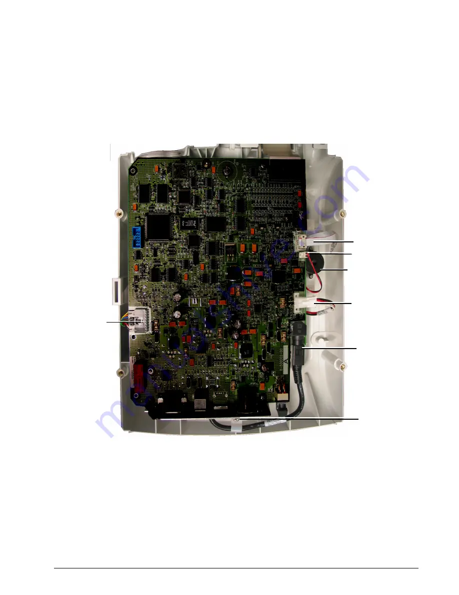
Follow these steps to remove the user interface PCB (Figure 8-10). Reverse to
install.
1. Remove top cover (section 8.2).
Figure 8-10: User Interface PCB
2. Disconnect these cables:
•
Switch control cable
•
Primary alarm connector
•
Battery cable (from battery housing)
•
Interconnect power cable (controller PCB) and retaining screw
•
Interprocessor communications cable
3. Remove the 4 screws from the spacer nuts.
Switch control cable
Primary alarm
connector
Interconnect
power cable
Interprocessor
communications
cable
Primary alarm
Battery cable
Retaining screw


